


5 Spindle Axis Operation
5.3.6 Tapping Applications
5-22
5.3.6
Tapping Applications
(1) Feed Hold Tap Return
If feed hold resistance is encountered during tapping, the tap may break off if the axis continues on without
stopping. To prevent this, decelerate the axis to a stop and return the axis in the opposite direction.
For the reversal, use interpolation to maintain the shape of the tap and stop the axis after execution of the
return operation has been completed.
(2) Specified Speed Return during Tapping
For large-diameter tapping, there is a difference in the cutting torque between the forward and return passes,
so the return spindle axis speed can be set to increase to a specified speed. The return interpolation speed is
also increased for the return operation.
However, speed is controlled so that the torque is not saturated.
(3) Deep Hole Tapping
During tapping, the tap can be repeatedly returned to remove any cutting chips and inserted again to tap deeper
in order to cut deep hole taps.
(4) Maximum Speed, Acceleration Time, and Acceleration/Deceleration of Tapping
Spindle Axes
The acceleration rate in position control (without torque saturation) must be sufficient enough to maintain lin-
earity.
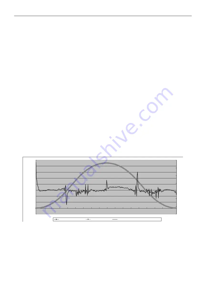
(5) Spindle Axis-based Feed Axis Synchronization Error Indicator for Tapping
To adjust and calibrate tapping properly, you must have some way to check the synchronization error of the
feed axis using the spindle axis as a base.
To achieve this, you need to develop an error indicator as shown below.
You must trace the difference between the positive value APOS
zs
of the tap position and the APOS feedback
position of the tap in regards to the APOS
s
revolution position of the spindle axis, then perform any adjust-
ments that are required to keep the synchronization error within the accuracy of the tap.
-20000000
0
20000000
40000000
60000000
80000000
100000000
120000000
140000000
160000000
1
21
41
61
81
101
121
141
161
181
201
221
241
261
281
301
321
341
-6
-4
-2
0
2
4
6
8
Synchronization error (0.001 mm) (mm*10
-3
)
Z axis FB (mm*10
-6
)
Spindle axis FB (rev*10
-6
)