


2.4 Operation Sequence
2-7
MECHA
TROLINK-
III
Communications
2.4
Operation Sequence
The operation sequence is the procedure for operating the servo drive through commands sent from the host
controller.
When cyclic communications start, the operation sequence is executed to operate the machine.
The operation sequence depends on whether the SERVOPACK parameters are managed by the host controller
or by the SERVOPACK.
Refer to
5.1 Operation Sequence for Managing Parameters Using a Controller
and
5.2 Operation Sequence
for Managing Parameters Using a SERVOPACK
in the
Σ
-V-SD Series User’s Manual MECHATROLINK-III
Standard Servo Profile Commands
(Manual No.: SIEP S800000 76) for details on operation sequences.
2.4.1
Operation Sequence When Parameters Are Managed by the Host Controller
Parameters are transferred to the SERVOPACK from the host controller after the power supply is turned ON.
Therefore, if parameters are changed at the host controller or if the SERVOPACK is replaced, the parameters
do not need to be set again.
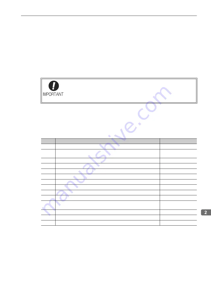
The operation sequence when parameters are managed by the host controller is given below.
Note: If the communications connection is disconnected properly, step 3 is not required.
If the communications connection is not disconnected properly, send the DISCONNECT command for at least two
communications cycles before you establish a connection again, and then send the CONNECT command in step 4.
A motor parameter file must be written to the SERVOPACK for the spindle motor, but with
the following operation sequence, the motor parameter file is not written.
To write the motor parameter file, use either the SigmaWin for
Σ
-V-SD (MT) or the drive
parameter upload/download function (refer to
8.2 SERVOPACK Parameter Uploading/
Downloading Functions
.
Step
Operation
Commands Used
1
Turn ON the control and main circuit power supplies.
–
2
Confirm that the SERVOPACK initialization has been completed (i.e., confirm
that SVCMD_STAT.M_RDY = 1).
NOP
3
Disconnect the previous communications connection.
DISCONNECT
4
Establish a communications connection and start counting WDT.
CONNECT
5
Read the device ID and other information.
ID_RD or MEM_RD
6
Read the device settings (e.g., parameters).
SVPRM_RD
7
Set the parameters required for the device.
SVPRM_WR
8
Enable the parameters that were set (setup).
CONFIG
9
Turn ON the power supply to the encoder and obtain the position data.
SENS_ON
10
Turn ON the servo.
SV_ON
11
Start operation.
INTERPOLATE,
VELCTRL, etc.
12
Turn OFF the servo.
SV_OFF
13
Disconnect communications.
DISCONNECT
14
Turn OFF the control and main circuit power supplies.
–