


9 Monitoring
9-12
9.4
Tapping Synchronization Accuracy Drawings
Tapping operations synchronize the operation of the spindle axis and feed axis (Z axis, etc.) to cut screw holes
in workpieces. This requires the confirmation of the synchronization accuracy of the spindle and feed axes.
The reference positions (CPOS) and coordinate positions (APOS) of the spindle and feed axes are used to
draw the reference and position, position error, and motor speed.
To determine the tapping synchronization error, you must check for the area where the synchronization error is
the greatest during the tapping operation.
A function to draw the tapping synchronization accuracy requires the following capabilities:
• Selection of the axes for which to perform the drawing (spindle and feed axes)
• Screw pitch (screw lead) setting for the tapping operation
*1
• Data acquisition cycle setting
*2
(sampling cycle and number of sampling points setting)
• Path data acquisition trigger setting
*3
• Drawing the tapping synchronization error
*4
• Synchronization error measurement and display of the greatest value
• Ability to save and load measured path data
• Overlay comparison of measured path data (i.e., the ability to load past data and overlay them on the current
data)
*5
∗1.
The host controller can automatically obtain the screw pitch with a G-code command.
∗2.
This depends on the data storage memory area of the host controller.
∗3.
A sequence that automatically activates a trigger to start data acquisition when the spindle axis or the feed axis begins
acceleration is recommended.
∗4.
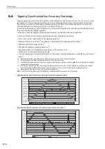
Plot the synchronization error between the spindle and feed axes in
μ
m. Plot the spindle axis position and spindle
axis motor speed together to determine where the margin of error is greatest during the tapping operation.
∗5.
Read the past data and overlay it on top of the current data.
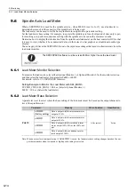
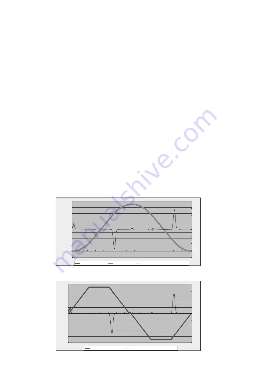
Refer to the following drawing of the tapping synchronization accuracy as a reference.
• Spindle Axis/Z Axis Positions and Tapping Synchronization Error
• Spindle Axis Motor Speed and Tapping Synchronization Error
-20,000,000
0
20,000,000
40,000,000
60,000,000
80,000,000
100,000,000
120,000,000
140,000,000
160,000,000
1
21
41
61
81
101
121
141
161
181
201
221
241
261
281
301
-80
-60
-40
-20
0
20
40
60
80
Synchronization error (0.001 mm) (mm*10
-3
)
Z axis FB (mm*10
-6
)
Spindle axis FB (rev*10
-6
)
-5,000
-4,000
-3,000
-2,000
-1,000
0
1,000
2,000
3,000
4,000
5,000
1
21
41
61
81
101
121
141
161
181
201
221
241
261
281
301
-80
-60
-40
-20
0
20
40
60
80
Synchronization error (0.001 mm) (mm*10
-3
)
Spindle axis FB speed [min
-1
]