


5 Spindle Axis Operation
5.5.1 How to Handle More than Four Sets of Gain Settings
5-24
5.5
Changing the Gain Selection Parameter
Spindle axes have three gear levels: high-speed, low-speed, and medium-speed, and sometimes they have spe-
cial replaceable attachments.
The appropriate gain must be selected to withstand the load for spindle axis gear conversion or when replacing
attachments for a gear.
The gain parameters are stored in the host controller and a specific gain area in the servo is overwritten as
required. Use the SVPRM_WR main command and subcommand to select the parameter number and change
the required parameter.
5.5.1
How to Handle More than Four Sets of Gain Settings
For example, if a mechanical gear has four settings: “Gear 1 (Low),” “Gear 2 (Middle),” “Gear 3 (High),” and
“not used,” the load that is incurred when different types of attachments are added will cause the gain to no
longer match.
If you know this can occur, you can temporarily change the gain to prevent this from happening.
Example
In this example, there are two different load possibilities for each gear, one with an attachment and one with-
out.
In this case, the gains must be set for the load when an attachment is present and when there is no attachment.
Gain 3 is assigned for the gain selection area for the “not used” gear as a software gain setting area. Gain 3 is
then selected when the SVPRM_WR command is used to write the gain setting to Gain 3.
When speed control is used to control a spindle axis, the tapping and orientation position loop gains are han-
dled by the host controller.
5.5.2
Gain Parameter Overwrite Timing for Tool Replacement (M06)
Gain parameter overwriting for tool replacement (M06) is performed when the spindle axis is stopped for tool
replacement.
The parameters for Gain 3 are overwritten when the orientation that is performed for the gain selection (0 to 3)
for the tool replacement has been completed and tool replacement has started.
When the M06 sequence starts, the gain number for the next tool is found from the gear and attachment tool
number. If the gain number is higher than 4, write that gain data to Gain 3 when the tool replacement orienta-
tion has been completed and the actual tool replacement begins. If the communications cycle is 250
μ
s, the
parameter write time will be approximately 7 to 8 ms.
Afterwards, if Gain 3 is selected after the tool has been replaced, all control after that point is executed with
the gain for that attachment tool.
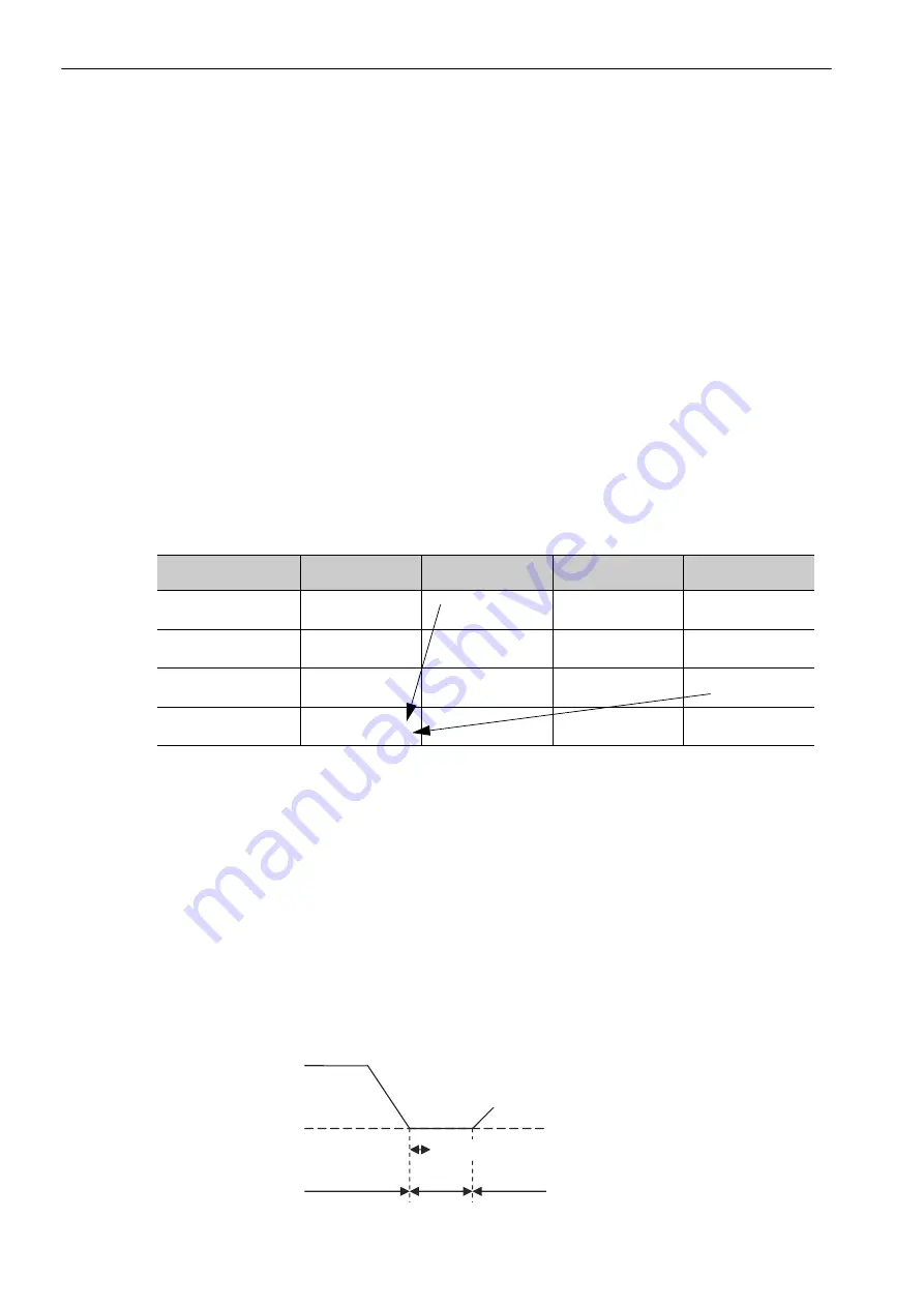
Gear Type
No ATT
ATT1
ATT2
ATT3
Gear 1 (low)
Gain 0
Software gain
(setting 1)
Software gain
(setting 4)
Software gain
(setting 7)
Gear 2 (medium)
Gain 1
Software gain
(setting 2)
Software gain
(setting 5)
Software gain
(setting 8)
Gear 3 (high)
Gain 2
Software gain
(setting 3)
Software gain
(setting 6)
Software gain
(setting 9)
Not used
(software gain setting)
Gain 3 (Pn12E)
Attachment tool
Tool
Orientation
Parameter changed.