


9.6 Spindle Axis Load Meter
9-15
Monitoring
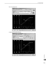
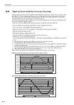
The following figure shows the relationship between the spindle motor (single-winding spindle motor and
winding-selection spindle motor) output characteristics and the load meter base setting.
(1) Single-winding Spindle Motor
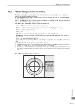
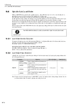
(2) Winding-selection Spindle Motor
The load meter reflects the output of the spindle motor, so it is in a state of constant change. Therefore, a filter
must be applied to the load meter monitor value when this value is displayed on the host controller.
You can use the following SERVOPACK parameters to set the filter.
Note: Set this parameter to 0 to disable the filter.
Speed [min
-1
]
3: Data is output with a continuous motor
rated output of 100%.
2: Data is output with the rated short-term
motor output as the 100% output.
1: Data is output with the maximum
motor output at 100%.
0: Data is output with the maximum
motor output at 120%.
Output [kW]
3: Data is output with a continuous
motor rated output of 100% (H).
2: Data is output with the rated short-term
motor output as the 100% output (H).
1: Data is output with the maximum
motor output at 100% (H).
Base speed (L)
Output characteristic for low-speed winding (L)
Output characteristic for high-speed winding (H)
0: Data is output with the maximum
motor output at 120% (H).
3: Data is output with a continuous
motor rated output of 100% (L).
2: Data is output with the rated short-term
motor output as the 100% output (L).
1: Data is output with the maximum
motor output at 100% (L).
Base speed (H)
Speed [min
-1
]
0: Data is output with the maximum
motor output at 120% (L).
Output [kW]
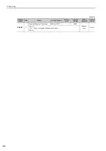
Parameter
No.
Name
Unit
Setting Range
Factory
Setting
When Enabled
Pn43F
Load Ratio Meter Filter Time Con-
stant
1
ms
0 to 5,000
100
Immediately