


4 Feed Axis Operation
4.1.3 Gain Selection (G-SEL)
4-8
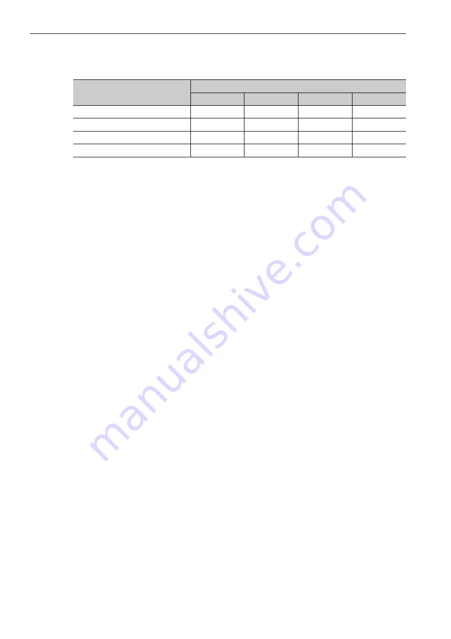
Gain Bank and Parameter Combinations
The gain parameters are selected based on the feed axis operation that is used (interpolation, high-speed feed-
ing, tap, etc.). Adjust the gain based on the feed axis operation that is used.
Example
• Cutting Operation
For cutting operations, set SVCMD_IO.G-SEL to 0 ((bit 11, bit 10, bit 9, bit 8) = (0, 0, 0, 0)) to select gain
bank 0.
Set Pn070.0 to 1 to enable predictive control. Set Pn070.1 to 1 to enable quadrant projection compensation.
• High-speed Feeding Operation
For high-speed feeding operations, set SVCMD_IO.G-SEL to 5 ((bit 11, bit 10, bit 9, bit 8) = (0, 1, 0, 1)) to
select gain bank 1.
Set Pn071.0 to 1 to enable internal speed feedforward. Set Pn071.0 to 2 to enable model following control.
• Spindle Axis Operation
For spindle axis operations, set SVCMD_IO.G-SEL to 10 ((bit 11, bit 10, bit 9, bit 8) = (1, 0, 1, 0)) to select
gain bank 2.
Synchronized Operation of Feed and Spindle Axes
In operations such as tapping, where the feed and spindle axes must be synchronized, you must match the
position loop gain for each of the axes. Failure to do so will result in increased synchronization error, which
will affect the operation.
If the gains for cutting operations (gain bank 0) are too large, you may not be able to set the same gains for the
spindle axis (doing so may result in vibration, for example). Design the system so gain bank 2 or 3 can be
selected for the feeding axis motion that needs to be synchronized with the spindle axis.
Gain Parameter
Gain Bank
0
1
2
3
Speed loop gain
Pn100
Pn104
Pn12B
Pn12E
Speed loop integral time constant
Pn101
Pn105
Pn12C
Pn12F
Position loop gain
Pn102
Pn106
Pn12D
Pn130
Torque reference filter
Pn401
Pn412
Pn413
Pn414