3 - 32
CHK
ADJ
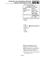
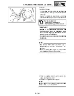
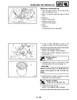
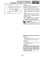
MEASURING THE COMPRESSION PRESSURE
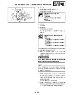
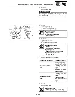
6. Install:
• compression gauge adapter
1
• compression gauge
2
7. Install:
• fuel tank
8. Measure:
• compression pressure
Out of specification
→
Refer to steps (c)
and (d).
▼▼▼
▼
▼ ▼▼▼
▼
▼ ▼▼▼
▼
▼ ▼▼▼
▼
▼ ▼▼▼
▼
▼ ▼▼▼
▼
▼▼▼
a. Set the main switch to “ON”.
b. With the throttle wide open, crank the
engine until the reading on the compression
gauge stabilizes.
WARNING
@
To prevent sparking, ground all spark plug
leads before cranking the engine.
NOTE:
@
The difference in compression pressure
between cylinders should not exceed 100 kPa
(1 kg/cm
2
, 14.22 psi).
c. If the compression pressure is above the
maximum specification, check the cylinder
head, valve surfaces and piston crown for
carbon deposits.
Carbon deposits
→
Eliminate.
d. If the compression pressure is below the
minimum specification, squirt a few drops of
oil into the cylinder and measure again.
Compression gauge set
14/18 mm
YU-33223
Compression gauge adapter
12 mm
YU-33223-3
Compression pressure (at sea
level)
Minimum
1,390 kPa (13.9 kg/cm
2
, 198 psi)
Standard
1,600 kPa (16.0 kg/cm
2
, 228 psi)
Maximum
1,790 kPa (17.9 kg/cm
2
, 255 psi)
Summary of Contents for FJR1300
Page 1: ...LIT 11616 16 18 5JW 28197 10 FJR1300R FJR1300RC SERVICE MANUAL ...
Page 6: ......
Page 82: ...2 22 SPEC TIGHTENING TORQUES Cylinder head tightening sequence Crankcase tightening sequence ...
Page 89: ...2 29 SPEC 1 Crankshaft 2 Main axle 3 Drive axle OIL FLOW DIAGRAMS ...
Page 90: ...2 30 SPEC 1 Oil nozzle 2 Main gallery bolt 3 Crankshaft OIL FLOW DIAGRAMS ...
Page 91: ...2 31 SPEC 1 Main axle 2 Drive axle 3 Oil delivery pipe OIL FLOW DIAGRAMS ...
Page 92: ...2 32 SPEC 1 Exhaust camshaft 2 Oil check bolt 3 Intake camshaft OIL FLOW DIAGRAMS ...
Page 94: ...2 34 SPEC 1 Crank pin 2 Crankshaft OIL FLOW DIAGRAMS ...
Page 97: ...2 37 SPEC 1 Main axle 2 Drive axle 3 Middle drive shaft OIL FLOW DIAGRAMS ...
Page 98: ...2 38 SPEC COOLING SYSTEM DIAGRAMS 1 Radiator COOLING SYSTEM DIAGRAMS ...
Page 99: ...2 39 SPEC 1 Water jacket joint 2 Oil cooler COOLING SYSTEM DIAGRAMS ...
Page 101: ...2 41 SPEC 1 Coolant reservoir 2 Radiator 3 Water pump COOLING SYSTEM DIAGRAMS ...
Page 107: ...2 47 SPEC CABLE ROUTING 1 Tail brake light lead ...
Page 196: ...3 80 CHK ADJ ADJUSTING THE HEADLIGHT BEAMS ...
Page 288: ...4 92 CHAS 3 Install bearing 1 to the swingarm Installed depth a 4 0 mm 0 16 in SWINGARM ...
Page 531: ...8 35 ELEC LIGHTING SYSTEM ...
Page 570: ......
Page 571: ...YAMAHA MOTOR CO LTD 2500 SHINGAI IWATA SHIZUOKA JAPAN PRINTED IN U S A ...


