2 - 9
SPEC
ENGINE SPECIFICATIONS
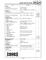
Clutch
Clutch type
Wet, multiple disc
----
Clutch release method
Hydraulic inner push
----
Operation
Left-hand operation
----
Clutch cable free play (at the end of
the clutch lever)
1.9 ~ 20.7 mm (0.075 ~ 0.815 in)
----
Friction plates
Thickness
2.9 ~ 3.1 mm (0.114 ~ 0.122 in)
2.8 mm
(0.1102 in)
Plate quantity
9
----
Clutch plates
Thickness
1.9 ~ 2.1 mm (0.075 ~ 0.083 in)
----
Plate quantity
8
----
Max. warpage
----
0.1 mm
(0.004 in)
Clutch spring
Free length
6.78 mm (0.2669 in)
----
Spring quantity
1
----
Min. length
----
6.44 mm
(0.2535 in)
Push rod bending limit
----
0.2 mm
(0.0079 in)
Transmission
Transmission type
Constant mesh, 5-speed
----
Primary reduction system
Helical gear
----
Primary reduction ratio
75/48 (1.563)
----
Secondary reduction system
Shaft drive
----
Secondary reduction ratio
35/36
×
21/27
×
33/9 (2.773)
----
Operation
Left-foot operation
----
Gear ratios
1st gear
43/17 (2.529)
----
2nd gear
39/22 (1.773)
----
3rd gear
31/23 (1.348)
----
4th gear
28/26 (1.077)
----
5th gear
26/28 (0.929)
----
Max. main axle runout
----
0.08 mm
(0.003 in)
Max. drive axle runout
----
0.08 mm
(0.003 in)
Shifting mechanism
Shift mechanism type
Shift drum and guide bar
----
Max. shift fork guide bar bending
----
0.1 mm
(0.0039 in)
Air filter type
Dry element
----
Item
Standard
Limit
Summary of Contents for FJR1300
Page 1: ...LIT 11616 16 18 5JW 28197 10 FJR1300R FJR1300RC SERVICE MANUAL ...
Page 6: ......
Page 82: ...2 22 SPEC TIGHTENING TORQUES Cylinder head tightening sequence Crankcase tightening sequence ...
Page 89: ...2 29 SPEC 1 Crankshaft 2 Main axle 3 Drive axle OIL FLOW DIAGRAMS ...
Page 90: ...2 30 SPEC 1 Oil nozzle 2 Main gallery bolt 3 Crankshaft OIL FLOW DIAGRAMS ...
Page 91: ...2 31 SPEC 1 Main axle 2 Drive axle 3 Oil delivery pipe OIL FLOW DIAGRAMS ...
Page 92: ...2 32 SPEC 1 Exhaust camshaft 2 Oil check bolt 3 Intake camshaft OIL FLOW DIAGRAMS ...
Page 94: ...2 34 SPEC 1 Crank pin 2 Crankshaft OIL FLOW DIAGRAMS ...
Page 97: ...2 37 SPEC 1 Main axle 2 Drive axle 3 Middle drive shaft OIL FLOW DIAGRAMS ...
Page 98: ...2 38 SPEC COOLING SYSTEM DIAGRAMS 1 Radiator COOLING SYSTEM DIAGRAMS ...
Page 99: ...2 39 SPEC 1 Water jacket joint 2 Oil cooler COOLING SYSTEM DIAGRAMS ...
Page 101: ...2 41 SPEC 1 Coolant reservoir 2 Radiator 3 Water pump COOLING SYSTEM DIAGRAMS ...
Page 107: ...2 47 SPEC CABLE ROUTING 1 Tail brake light lead ...
Page 196: ...3 80 CHK ADJ ADJUSTING THE HEADLIGHT BEAMS ...
Page 288: ...4 92 CHAS 3 Install bearing 1 to the swingarm Installed depth a 4 0 mm 0 16 in SWINGARM ...
Page 531: ...8 35 ELEC LIGHTING SYSTEM ...
Page 570: ......
Page 571: ...YAMAHA MOTOR CO LTD 2500 SHINGAI IWATA SHIZUOKA JAPAN PRINTED IN U S A ...

