4 - 5
CHAS
FRONT WHEEL AND BRAKE DISCS
EAS00533
CHECKING THE BRAKE DISCS
The following procedure applies to all of the
brake discs.
1. Check:
• brake disc
Damage/galling
→
Replace.
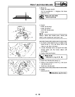
2. Measure:
• brake disc deflection
Out of specification
→
Correct the brake
disc deflection or replace the brake disc.
▼▼▼
▼
▼ ▼▼▼
▼
▼ ▼▼▼
▼
▼ ▼▼▼
▼
▼ ▼▼▼
▼
▼ ▼▼▼
▼
▼▼▼
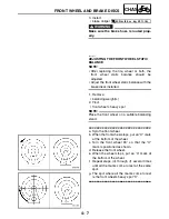
a. Place the motorcycle on a suitable stand so
that the wheel is elevated.
b. Before measuring the front brake disc
deflection, turn the handlebars to the left or
right to ensure that the front wheel is sta-
tionary.
c. Remove the brake caliper.
d. Hold the dial gauge at a right angle against
the brake disc surface.
e. Measure the deflection 1.5 mm (0.059 in)
below the edge of the brake disc.
▲▲▲
▲
▲ ▲▲▲
▲
▲ ▲▲▲
▲
▲ ▲▲▲
▲
▲ ▲▲▲
▲
▲ ▲▲▲
▲
▲▲▲
Brake disc deflection limit (maxi-
mum)
Front: 0.1 mm (0.004 in)
Rear: 0.1 mm (0.004 in)
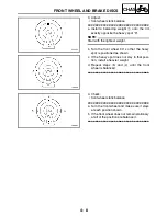
3. Measure:
• brake disc thickness
Measure the brake disc thickness at a few
different locations.
Out of specification
→
Replace.
Brake disc thickness limit (mini-
mum)
Front: 4.5 mm (0.18 in)
Rear: 5.5 mm (0.22 in)
Summary of Contents for FJR1300
Page 1: ...LIT 11616 16 18 5JW 28197 10 FJR1300R FJR1300RC SERVICE MANUAL ...
Page 6: ......
Page 82: ...2 22 SPEC TIGHTENING TORQUES Cylinder head tightening sequence Crankcase tightening sequence ...
Page 89: ...2 29 SPEC 1 Crankshaft 2 Main axle 3 Drive axle OIL FLOW DIAGRAMS ...
Page 90: ...2 30 SPEC 1 Oil nozzle 2 Main gallery bolt 3 Crankshaft OIL FLOW DIAGRAMS ...
Page 91: ...2 31 SPEC 1 Main axle 2 Drive axle 3 Oil delivery pipe OIL FLOW DIAGRAMS ...
Page 92: ...2 32 SPEC 1 Exhaust camshaft 2 Oil check bolt 3 Intake camshaft OIL FLOW DIAGRAMS ...
Page 94: ...2 34 SPEC 1 Crank pin 2 Crankshaft OIL FLOW DIAGRAMS ...
Page 97: ...2 37 SPEC 1 Main axle 2 Drive axle 3 Middle drive shaft OIL FLOW DIAGRAMS ...
Page 98: ...2 38 SPEC COOLING SYSTEM DIAGRAMS 1 Radiator COOLING SYSTEM DIAGRAMS ...
Page 99: ...2 39 SPEC 1 Water jacket joint 2 Oil cooler COOLING SYSTEM DIAGRAMS ...
Page 101: ...2 41 SPEC 1 Coolant reservoir 2 Radiator 3 Water pump COOLING SYSTEM DIAGRAMS ...
Page 107: ...2 47 SPEC CABLE ROUTING 1 Tail brake light lead ...
Page 196: ...3 80 CHK ADJ ADJUSTING THE HEADLIGHT BEAMS ...
Page 288: ...4 92 CHAS 3 Install bearing 1 to the swingarm Installed depth a 4 0 mm 0 16 in SWINGARM ...
Page 531: ...8 35 ELEC LIGHTING SYSTEM ...
Page 570: ......
Page 571: ...YAMAHA MOTOR CO LTD 2500 SHINGAI IWATA SHIZUOKA JAPAN PRINTED IN U S A ...


