4 - 94
CHAS
SHAFT DRIVE
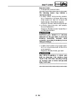
Inspection notes
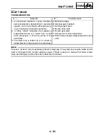
1. Investigate any unusual noises.
▼▼▼
▼
▼ ▼▼▼
▼
▼ ▼▼▼
▼
▼ ▼▼▼
▼
▼ ▼▼▼
▼
▼ ▼▼▼
▼
▼▼▼
The following noises may indicate a
mechanical defect:
a. A rolling “rumble” during coasting, accelera-
tion or deceleration (increases with the rear
wheel speed, but does not increase with
higher engine or transmission speeds).
Diagnosis: Possible wheel bearing damage
b. A whining noise that varies with accelera-
tion and deceleration.
Diagnosis: Possible incorrect reassembly or
too little gear backlash
WARNING
@
Insufficient gear backlash is extremely
destructive to the gear teeth. If a test ride,
following reassembly, indicates these
symptoms, stop riding immediately to mini-
mize gear damage.
@
c. A slight “clunk” evident at low speed opera-
tion (not to be confused with normal motor-
cycle operation).
Diagnosis: Possible broken gear teeth
WARNING
@
Stop riding immediately if broken gear
teeth are suspected. This condition could
result in the shaft drive assembly locking
up, causing a loss of control and possible
injury to the rider.
@
▲▲▲
▲
▲ ▲▲▲
▲
▲ ▲▲▲
▲
▲ ▲▲▲
▲
▲ ▲▲▲
▲
▲ ▲▲▲
▲
▲▲▲
Summary of Contents for FJR1300
Page 1: ...LIT 11616 16 18 5JW 28197 10 FJR1300R FJR1300RC SERVICE MANUAL ...
Page 6: ......
Page 82: ...2 22 SPEC TIGHTENING TORQUES Cylinder head tightening sequence Crankcase tightening sequence ...
Page 89: ...2 29 SPEC 1 Crankshaft 2 Main axle 3 Drive axle OIL FLOW DIAGRAMS ...
Page 90: ...2 30 SPEC 1 Oil nozzle 2 Main gallery bolt 3 Crankshaft OIL FLOW DIAGRAMS ...
Page 91: ...2 31 SPEC 1 Main axle 2 Drive axle 3 Oil delivery pipe OIL FLOW DIAGRAMS ...
Page 92: ...2 32 SPEC 1 Exhaust camshaft 2 Oil check bolt 3 Intake camshaft OIL FLOW DIAGRAMS ...
Page 94: ...2 34 SPEC 1 Crank pin 2 Crankshaft OIL FLOW DIAGRAMS ...
Page 97: ...2 37 SPEC 1 Main axle 2 Drive axle 3 Middle drive shaft OIL FLOW DIAGRAMS ...
Page 98: ...2 38 SPEC COOLING SYSTEM DIAGRAMS 1 Radiator COOLING SYSTEM DIAGRAMS ...
Page 99: ...2 39 SPEC 1 Water jacket joint 2 Oil cooler COOLING SYSTEM DIAGRAMS ...
Page 101: ...2 41 SPEC 1 Coolant reservoir 2 Radiator 3 Water pump COOLING SYSTEM DIAGRAMS ...
Page 107: ...2 47 SPEC CABLE ROUTING 1 Tail brake light lead ...
Page 196: ...3 80 CHK ADJ ADJUSTING THE HEADLIGHT BEAMS ...
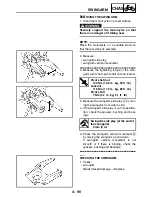
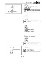
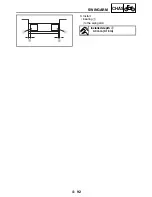
Page 288: ...4 92 CHAS 3 Install bearing 1 to the swingarm Installed depth a 4 0 mm 0 16 in SWINGARM ...
Page 531: ...8 35 ELEC LIGHTING SYSTEM ...
Page 570: ......
Page 571: ...YAMAHA MOTOR CO LTD 2500 SHINGAI IWATA SHIZUOKA JAPAN PRINTED IN U S A ...

