


66 •
750-671 [Steppercontroller]
Configuration
WAGO-I/O-SYSTEM
750
I/O
Modules
Note
A linkable bit can also be linked to another linkable bit, but the maximum
number of nesting levels is four (4). Too many nesting levels will yield an
ambiguous result and the error ERR_LINK_NESTING will be issued.
Note
The nesting levels are not checked until the system run time.
Linking of bits is performed in the device configuration and can only be
changed by reconfiguration. An exception to this rule are the bits that are
linked to MZERO and MONE. These bits can be set or reset as often as
required during operation using mailbox commands of the Move program.
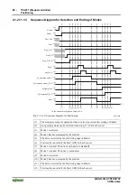
The example below provides an illustration of this:
Input 2 is normally set as the reference input. However, in a certain
application is may be more advantageous to use Input 2 for specifying the
direction of movement for the Jog mode. Moreover, a "1" at the input should
signify that the motor is moving in a positive direction.
The address and length of the configuration variables are given in the
appendix in section 3.5, „Configuration Variables“.
Address
Configuration
variable
Dec.
Hex.
Data
type
Default
Range
Description
…
Ptr_FILT1
168
0xA8 UINT8 0x00
0 ... 255 Source for linkable bit 0xA8
...
Ptr_Direction_
Neg
187
0xBB UINT8 0x53
0 ... 255 Source for linkable bit 0xBB
…
Filter1_Function 224 0xE0 UINT8 0
0 ... 11
Function of filter:
1 = inversion
…


