7.1
95-8533
4-21
SYSTEM STARTUP
PRE-OPERATION CHECKS
General
Insulate all shields to prevent shorts to device housing
or to any other conductor.
Place alarm/release output in “Bypass/Isolate” when
servicing devices.
Maintain a log book containing the type and serial
numbers of devices as well as the location and date
of installation.
Maintain a log of maintenance activities.
Observe normal precautions for handling electrostatic
sensitive devices.
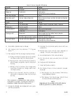
LON
Rocker switches for each LON device must be set to
the desired address prior to power-up.
Test the loop with no power applied. DC resistance
should be equal on A and B.
Check polarity on A and B (no rolls). COM 1 connects
to COM 2; COM 2 connects to COM 1. A connects
to A and B to B.
Measure voltage. A to chassis ground measures
approximately +7.5 vdc. B to ground measures
approximately –7.5 vdc.
Measure signal (400 mv P-P min.). (Use oscilloscope
if possible).
Check fault tolerance by introducing a short.
Controller
The I/O and LON wiring is correctly installed,
observing polarity. All cable shields are properly
terminated and insulated.
Power wiring is installed and power source is
operational.
Chassis ground stud must be connected to earth
ground.
Redundant Controller
The I/O and LON wiring is correctly installed,
observing polarity. All cable shields are properly
terminated and insulated.
Power wiring is installed and power source is
operational.
Chassis ground stud must be connected to earth
ground.
The HSSL cable is connected between the two
controllers.
EDIO/DCIO Module
Verify correct address setting.
Check signal circuits for correct polarity.
Check for correct installation of EOL resistors.
Relay Module
Verify correct address setting.
Check for correct output connections.
Analog Input Module
Verify correct address setting.
Check for correct input connections.
Check each channel with a loop current input.
Intelligent Protection Module
Verify correct address setting.
Check for correct input/output connections.
Power Supplies and Power Monitors
Verify all earth ground connections as specified in the
wiring instructions.
Verify correct ac power to supply.
Check power distribution to ensure that all devices
are receiving power.
Check power trouble indicator by introducing an open
to the battery.
Summary of Contents for DET-TRONICS 95-8533
Page 128: ...7 1 95 8533 A 4 Figure A 1 System Drawing 007545 001 ...
Page 129: ...95 8533 A 5 7 1 Figure A 2 System Drawing 007545 001 ...
Page 131: ...95 8533 7 1 B 2 Figure B 1 Drawing 007546 001 ...
Page 132: ...95 8533 7 1 B 3 Figure B 2 Drawing 007546 001 ...
Page 134: ...95 8533 7 1 C 2 Figure C 1 Drawing 007547 001 ...
Page 141: ...95 8533 7 1 D 7 Figure D1 System Drawing 007545 001 ...
Page 143: ...APPENDIX E E 1 95 8533 7 1 ...


