3-9
7.1
95-8533
IMPORTANT!
D e t - Tr o n i c s
recommends the use of
shielded cable (required by CeNeLeC) to
prevent external electromagnetic interference
from affecting field devices.
IMPORTANT!
Be sure that
the selected cable meets the
specifications. The use of other cable types can
degrade system operation. If necessary, consult
factory for further suggested cable types.
1. Remove the cover from the Network Extender
enclosure.
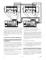
2. Connect 24 vdc power lead wires and
communication network cable to the terminal
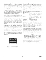
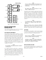
block. (See Figure 3-2 for terminal location and
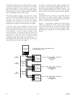
Figure 3-3 for terminal identification).
See Table 3-8 to determine maximum wiring
length.
COM 1 -
Communication network connections:
Connect to COM 2 terminals of the next
device on the loop, A to A and B to B.
COM 2 -
Communication network connections:
Connect to COM 1 terminals of the
previous device on the loop, A to A and
B to B.
24 VDC -
Connect the "+" terminal to the positive
side of the 24 vdc power source. (Both
"+" terminals are connected internally.)
Connect the "–" terminal to the negative
side of the 24 vdc power source. (Both
"–" terminals are connected internally.)
3. Connect shields to the designated "shield"
terminals. The two shield terminals are connected
internally to ensure shield continuity.
CAUTION!
Do not
ground either shield at the network
extender enclosure. Insulate the shields to
prevent shorting to the device housing or to any
other conductor.
4. Check ALL wiring to ensure that proper
connections have been made.
5. Inspect the junction box O-ring to be sure that it is
in good condition.
6. Lubricate the O-ring and the threads of the
junction box cover with a thin coat of grease to
ease installation and ensure a watertight
enclosure.
NOTe
The recommended lubricant is a silicone free
grease, available from Det-Tronics.
7. Place the cover on the enclosure. Tighten only
until snug.
Do not over tighten.
TERMINAL NO. 1
1
12
A2021
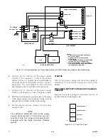
Figure 3-2—Network Extender Wiring Terminal Location
Table 3-8—Maximum Wiring Length from Nominal 24 vdc
Power Source to Network Extender (Maximum wire lengths are
based upon the cable’s physical and electrical characteristics.)
Wire Size
Maximum Wiring Distance
Feet
Meters
18 AWG (1.0 mm2)*
2200
650
16 AWG (1.5 mm2)*
3500
750
14 AWG (2.5 mm2)*
5600
1700
* Approximate Metric Equivalent.
Summary of Contents for DET-TRONICS 95-8533
Page 128: ...7 1 95 8533 A 4 Figure A 1 System Drawing 007545 001 ...
Page 129: ...95 8533 A 5 7 1 Figure A 2 System Drawing 007545 001 ...
Page 131: ...95 8533 7 1 B 2 Figure B 1 Drawing 007546 001 ...
Page 132: ...95 8533 7 1 B 3 Figure B 2 Drawing 007546 001 ...
Page 134: ...95 8533 7 1 C 2 Figure C 1 Drawing 007547 001 ...
Page 141: ...95 8533 7 1 D 7 Figure D1 System Drawing 007545 001 ...
Page 143: ...APPENDIX E E 1 95 8533 7 1 ...


