7.1
3-24
95-8533
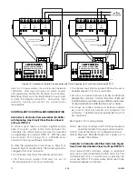
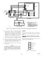
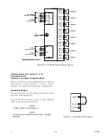
6. Connect the “B” terminal on the power supply
monitor to the negative (–) side of the backup
battery. Connect a correctly sized circuit breaker or
disconnect switch in the battery circuit as shown in
Figure 3-21. If a circuit breaker is used, it must be
rated between 150% and 250% of the total load.
7. Connect the “C” terminal on the power supply
monitor to the negative (–) side of the power supply.
8. Wire the power distribution circuit breakers to the output
of the power supply. Circuit breaker ratings must be
between 150% and 250% of the full load rating.
9. Set the device network address for the power
supply monitor.
NOTe
For additional information, refer to the power
supply manufacturer’s instruction manual
provided with the support documentation
received with the eagle Quantum Premier
system.
STARTUP
Turn on the power supply and allow the voltage to
stabilize at 27 volts before closing the circuit to the
battery.
MEASURING BATTERY vOLTAGE AND CHARGING
CURRENT
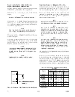
Measure the battery voltage at terminals 3 and 4 of
terminal block J2. See Figure 3-22.
1
4
C
B
AC BREAKER
DC BREAKER
H
N
G
–
+
24 VDC
OUTPUT
POWER SUPPLY MONITOR
12
11
10
9
8
7
6
5
4
3
2
1
POWER SUPPLY
–
+
12 VDC
–
+
12 VDC
NRTL CABINET
BATTERY
CIRCUIT
BREAKER
–
+
–
–
–
–
+
+
+
+
POWER DIST CKT #1
POWER DIST CKT #2
POWER DIST CKT #3
POWER DIST CKT #4
NOTES
1. AC INPUT SELECTABLE (THROUGH THE OIS)
FOR 120 / 208 / 240 VAC.
2. BATTERY SIZE CALCULATED BASED ON
SYSTEM LOAD.
3. CIRCUIT BREAKER RATINGS MUST BE BETWEEN
150% AND 250% OF FULL LOAD RATING.
4. REMOVAL OF TERMINAL PLUG WITH POWER
APPLIED TO TERMINALS B AND C WILL DAMAGE
THE POWER SUPPLY MONITOR.
D1951
AC MONITOR
BACKUP BATTERIES
AC POWER
See Notes 1 & 3
See Note 3
See Note 2
See Note 4
Figure 3-21— Wiring Connections for a Power Supply Monitor, EQ21XXPS Series Power Supply and Backup Batteries
A1952
1
2
3
4
CURRENT SENSE
+
BATTERY
+
CURRENT SENSE
–
BATTERY
–
Figure 3-22—J2: Current Test Points
Summary of Contents for DET-TRONICS 95-8533
Page 128: ...7 1 95 8533 A 4 Figure A 1 System Drawing 007545 001 ...
Page 129: ...95 8533 A 5 7 1 Figure A 2 System Drawing 007545 001 ...
Page 131: ...95 8533 7 1 B 2 Figure B 1 Drawing 007546 001 ...
Page 132: ...95 8533 7 1 B 3 Figure B 2 Drawing 007546 001 ...
Page 134: ...95 8533 7 1 C 2 Figure C 1 Drawing 007547 001 ...
Page 141: ...95 8533 7 1 D 7 Figure D1 System Drawing 007545 001 ...
Page 143: ...APPENDIX E E 1 95 8533 7 1 ...


