7.1
95-8533
2-9
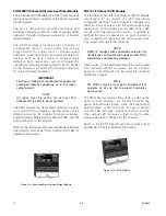
EQ3720 8 Channel Relay module
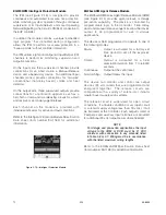
The 8 Channel Relay Module (see Figure 2-11)
consists of eight individually configured output
channels.
note
the relay module only supports equipment that
operates on 24 vdc (not to exceed 2 amperes) at
each output channel.
The relay module has two LEDs for the device and
two LEDs for each channel. On the device level, one
green LED indicates power, while the other amber
LED indicates a LON CPU fault. For each channel,
one red LED indicates channel activation and the
other amber LED indicates that the module operating
voltage is low or that the module has not been
configured (all eight channel LEDs blink).
Refer to the Relay Module Specification Data sheet
(form number 90-1181) for additional information.
EQ3710aim analog input module
The 8 Channel Analog Input Module (see Figure 2-12)
provides a means of connecting devices with a
calibrated 4-20 mA output signal to the Eagle
Quantum Premier System.
The Analog Input Module (AIM) provides 8
configurable channels that can be set for either
combustible gas mode or universal mode. The
combustible gas mode provides a number of
automatically programmed settings, and alarm
thresholds that are limited to approval body
requirements. The universal mode is used for generic
devices where control over all configuration
parameters is required. All devices must provided
their own calibration facilities.
For fire detector 4-20 mA inputs, the Analog Input
Module (AIM) is certified for use as an NFPA 72 Class
B, Style B Approved input.
Refer to the Analog Input Module Specification Data
sheet (form number 90-1183) for additional
information.
Figure 2-12—Eight Channel Analog Input Module
Figure 2-11—Eight Channel Relay Module
Summary of Contents for DET-TRONICS 95-8533
Page 128: ...7 1 95 8533 A 4 Figure A 1 System Drawing 007545 001 ...
Page 129: ...95 8533 A 5 7 1 Figure A 2 System Drawing 007545 001 ...
Page 131: ...95 8533 7 1 B 2 Figure B 1 Drawing 007546 001 ...
Page 132: ...95 8533 7 1 B 3 Figure B 2 Drawing 007546 001 ...
Page 134: ...95 8533 7 1 C 2 Figure C 1 Drawing 007547 001 ...
Page 141: ...95 8533 7 1 D 7 Figure D1 System Drawing 007545 001 ...
Page 143: ...APPENDIX E E 1 95 8533 7 1 ...

