7.1
3-32
95-8533
8 CHANNEL DISCRETE INPUT/
OUTPUT (DCIO) MODULE
INSTALLATION
The following paragraphs describe how to properly
install and configure the 8 Channel DCIO Module.
MOUNTING
The DCIO must be properly installed in a suitable
enclosure that is rated for the location. The enclosure
must provide space to install and wire the DCIO
module and must also provide for ground wire
termination. Access into the enclosure is gained by
using a special tool to open the enclosure. The
enclosure should be rated for the temperature range
of the location plus the temperature rise of all
equipment installed inside the enclosure. The
enclosure must be rated for electrical equipment that
is going to be installed.
The DCIO can be panel or DIN rail mounted.
NOTe
It is recommended to maintain a minimum of 4
inches clearance between the module and other
equipment to provide adequate room for wiring
and ventilation.
WIRING
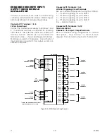
All electrical connections are made to the field wiring
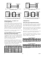
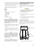
connectors furnished with the module. See Figure
3-38 below for terminal identification.
Power Connector, Terminals 1 to 6
24 vdc Power Input
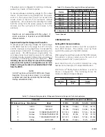
Power connections to the DCIO depend upon the total
current consumption of all the channels in the device.
Each output-configured channel can consume up to 2
Amps. The power-input connection made through the
terminal plug is rated to handle up to 10 Amps. If the
total current draw is more than 10 Amps, power must
be provided into the device using both power inputs.
In this case, connect the power supply to terminals 1
and 2, and also to 4 and 5. Otherwise connect the
power supply to terminals 1 and 2. Power wire
shielding should be connected to terminals 3 and 6.
1 — +
2 — –
3 — Shield*
4 — +
5 — –
6 — Shield*
*Shields on power wires are optional unless required
by local codes.
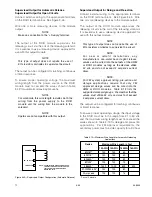
Connect the module power supply to terminals 1 and
2. If additional terminals are required for powering
other devices, these devices should be connected to
terminals 4 and 5. Shields are to be connected to
terminals 3 and 6.
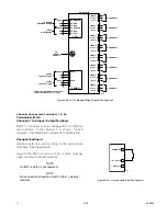
COM Connector, Terminals 1 to 6
LON Terminals
Be sure to observe polarity when wiring the LON.
1 — "A" side of signaling circuit for COM 1
2 — "B" side of signaling circuit for COM 1
4 — "A" side of signaling circuit for COM 2
5 — "B" side of signaling circuit for COM 2
3 & 6 — shield connections.
Summary of Contents for DET-TRONICS 95-8533
Page 128: ...7 1 95 8533 A 4 Figure A 1 System Drawing 007545 001 ...
Page 129: ...95 8533 A 5 7 1 Figure A 2 System Drawing 007545 001 ...
Page 131: ...95 8533 7 1 B 2 Figure B 1 Drawing 007546 001 ...
Page 132: ...95 8533 7 1 B 3 Figure B 2 Drawing 007546 001 ...
Page 134: ...95 8533 7 1 C 2 Figure C 1 Drawing 007547 001 ...
Page 141: ...95 8533 7 1 D 7 Figure D1 System Drawing 007545 001 ...
Page 143: ...APPENDIX E E 1 95 8533 7 1 ...

