7.1
95-8533
6-10
EQP2120PS(–B) POWER SUPPLIES
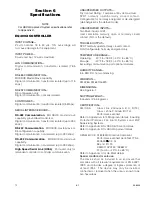
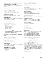
INPUT VOLTAGE—
Auto-selectable for 120/220 vac input power,
–15, +10%.
frEQUENcY rANGE—
60/50 Hz, single phase.
INPUT cUrrENT—
Vout = 24.5 Vdc:
4.9 Amps @ 120 Vac
2.9 Amps @ 220 Vac.
Vout = 28.0 Vdc:
5.6 Amps @ 120 Vac
3.2 Amps @ 220 Vac.
OUTPUT VOLTAGE—
24.5 Vdc nominal, 24.5 to 28.0 Vdc.
OUTPUT cUrrENT—
20 amperes.
POwEr cONSUmPTION—
67 Watts maximum @ 120 Vac.
70 Watts maximum @ 220 Vac.
TEmPErATUrE rANGE—
Operating: +32°F to +122°F (0°C to +50°C)
(Model –B): +32°F to +131°F (0°C to +55°C)
Storage:
-40°F to +185°F (-40°C to +85°C).
HUmIdITY rANGE—
5 to 95% RH at 25°C, non-condensing.
dImENSIONS—
in Inches (Centimeters)
Width
Height
Depth
6.2 (15.7)
5.2 (13.0)
5.0 (12.5)
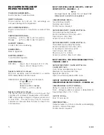
note
Power supplies are designed for DIn rail or
panel mounting (–B suffix).
cErTIfIcATION—
FM / CSA: Ordinary locations.
Refer to Appendix D for USCG Approval details.
REDUNDANCY MODULE QUINT–DIODE/40
TEmPErATUrE rANGE—
Operating:
+32°F to +122°F (0°C to +50°C)
Marine Applications: +32°F to +131°F (0°C to +55°C)
Storage:
-40°F to +185°F (-40°C to +85°C).
HUmIdITY rANGE—
5 to 95% RH, non-condensing.
dImENSIONS—
in Inches (Centimeters)
Width
Height
Depth
2.4 (6.2)
4 (10.2)
3.3 (8.4)
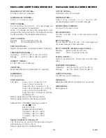
EQ21XXPSM POWER SUPPLY MONITOR
INPUT VOLTAGE—
24 vdc nominal, 18 to 30 Vdc.
POwEr cONSUmPTION—
2.0 watts maximum.
mEASUrEmENT rANGE—
AC Voltage:
240 vac maximum.
DC Battery Charging Current: 75 amperes maximum.
OUTPUT—
Digital communication, transformer isolated (78.5 k bps).
TEmPErATUrE rANGE—
Operating: +32°F to +122°F (0°C to +50°C)
Storage:
–67°F to +185°F (–55°C to +85°C).
HUmIdITY rANGE—
5 to 95% RH, non-condensing.
dImENSIONS—
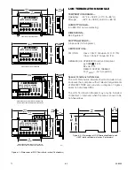
See Figure 6-4.
cErTIfIcATION—
FM / CSA: Ordinary locations.
B
C
J1
J3
4
(10.2)
8.5
(21.6)
9
(22.9)
2.5
(6.4)
2.25
(5.7)
A2038
figure 6-4—dimensions of Power Supply monitor in Inches (cm)
Summary of Contents for DET-TRONICS 95-8533
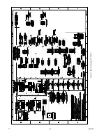
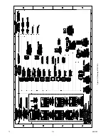
Page 128: ...7 1 95 8533 A 4 Figure A 1 System Drawing 007545 001 ...
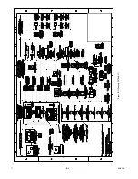
Page 129: ...95 8533 A 5 7 1 Figure A 2 System Drawing 007545 001 ...
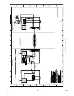
Page 131: ...95 8533 7 1 B 2 Figure B 1 Drawing 007546 001 ...
Page 132: ...95 8533 7 1 B 3 Figure B 2 Drawing 007546 001 ...
Page 134: ...95 8533 7 1 C 2 Figure C 1 Drawing 007547 001 ...
Page 141: ...95 8533 7 1 D 7 Figure D1 System Drawing 007545 001 ...
Page 143: ...APPENDIX E E 1 95 8533 7 1 ...

