7.1
95-8533
4-20
EQ25xxARM AGENT RELEASE MODULE
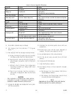
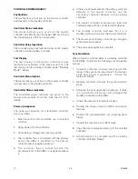
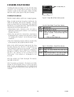
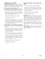
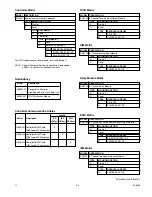
The EQ25xxARM has three LEDs to indicate device
status. They are located at the center of the circuit
board.
EQ25xxSAM SIGNAL AUDIBLE MODULE
The EQ25xxSAM has three LEDs to indicate device
status. They are located at the center of the circuit
board.
EQ24xxNE Network Extender
The EQ24xxNE has three LEDs (one green, two
amber) for indicating device status.
LED
Device Status
Green
When On indicates device has power.
Red
When On steady indicates an output is
activated.
When Blinking at a 4 Hz rate with the LED on
50%, off 50% of the time indicates a local
trouble condition such as an open output
circuit or low solenoid supply voltage.
When Blinking at a 1 Hz rate with the LED on
5%, off 95% of the time indicates an isolate
condition.
When Blinking at a 1 Hz rate with the LED on
95%, off 5% of the time indicates release and
isolate.
Amber
When On indicates a malfunction in the
electronic circuitry. Module replacement is
required.
Table 4-18—Agent Release Module Status Indicators
LED
Device Status
Green
When On indicates device has power.
Flashes to indicate messages are being transferred
over the LON.
Amber
When On indicates a malfunction in the electronic
circuitry. Module replacement is required.
Note
When a network extender has an internal
fault, the message display will only indicate
that there is a LoN fault condition existing
somewhere on the LoN.
Table 4-20—Network Extender Status Indicators
LED
Device Status
Green
When On indicates device has power.
Red
When On steady indicates an Active condition exists.
When Blinking indicates a Trouble condition exists.
Amber
When On indicates a malfunction in the electronic
circuitry. Module replacement is required.
Table 4-19—Signal Audible Module Status Indicators
Summary of Contents for DET-TRONICS 95-8533
Page 128: ...7 1 95 8533 A 4 Figure A 1 System Drawing 007545 001 ...
Page 129: ...95 8533 A 5 7 1 Figure A 2 System Drawing 007545 001 ...
Page 131: ...95 8533 7 1 B 2 Figure B 1 Drawing 007546 001 ...
Page 132: ...95 8533 7 1 B 3 Figure B 2 Drawing 007546 001 ...
Page 134: ...95 8533 7 1 C 2 Figure C 1 Drawing 007547 001 ...
Page 141: ...95 8533 7 1 D 7 Figure D1 System Drawing 007545 001 ...
Page 143: ...APPENDIX E E 1 95 8533 7 1 ...


