7.1
95-8533
6-5
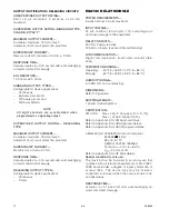
EQ3700 DISCRETE IO (DCIO)
MODULE
POwEr rEQUIrEmENTS—
3 watts nominal, 7 watts maximum.
INPUT VOLTAGE—
24 vdc nominal, 18 to 30 vdc. 10% overvoltage will
not cause damage to the equipment.
21 to 30 vdc for Pre-action / Deluge application.
NOTE: For deluge and pre-action applications, input
voltage to the device must be 21 vdc minimum to ensure
proper operation of the connected output device.
OUTPUT VOLTAGE—
(Input voltage – 0.5 vdc) @ 2 amperes.
LON cOmmUNIcATION—
Digital communication, transformer isolated (78.5
kbps).
TEmPErATUrE rANGE—
Operating: –40°F to +185°F (–40°C to +85°C).
Storage:
–67°F to +185°F (–55°C to +85°C).
HUmIdITY rANGE—
5 to 95% RH, non-condensing.
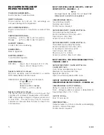
dImENSIONS—
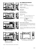
Refer to Figure 6-3.
SHIPPING wEIGHT—
1 pound (0.45 kilograms).
cErTIfIcATION—
FM / CSA: Class I, Div. 2, Groups A, B, C, D (T4).
Class I, Zone 2, Group IIC (T4).
Refer to Appendix A for FM Approval details.
Refer to Appendix B for CSA Approval details.
CENELEC/CE: ATEX/EMC Directive Compliant.
0539
FM
®
II 3 G
EEx nC IIC T4
DEMKO 02 ATEX 133864U
T4 (Tamb = –40°C to +85°C).
Refer to Appendix C for CE Mark details.
Special conditions for safe use:
The device shall be installed in an enclosure that
complies with all relevant requirements of EN 50021:
1999, and provides a degree of ingress protection of
at least IP54. The device may only be installed,
connected or removed when the area is known to be
non-hazardous.
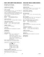
INPUT / INITIATING DEVICE CIRCUITS
UNSUPErVISEd INPUT—
Two state input (on/off).
Normally open contact.
SUPErVISEd INPUT, cLASS b STYLE b—
Two state input (active/trouble):
– End of Line Resistor 10 K ohms nominal
– Open Circuit > 45 K ohms
– Active Circuit < 5 K ohms.
SUPErVISEd INPUT, cLASS b STYLE c—
Three State input (active/short/open):
– End of Line Resistor 10 K ohms nominal
– In Line Resistor 3.3 K ohms nominal
– Open Circuit > 45 K ohms
– Short Circuit < 1.4 K ohms
– Active Circuit 2.5 K ohms to 5 K ohms.
INPUT, TYPES—
Configurable for fixed logic applications:
– Fire Alarm
– Supervisory
– Trouble
– High Gas Alarm
– Low Gas Alarm
– Other.
Summary of Contents for DET-TRONICS 95-8533
Page 128: ...7 1 95 8533 A 4 Figure A 1 System Drawing 007545 001 ...
Page 129: ...95 8533 A 5 7 1 Figure A 2 System Drawing 007545 001 ...
Page 131: ...95 8533 7 1 B 2 Figure B 1 Drawing 007546 001 ...
Page 132: ...95 8533 7 1 B 3 Figure B 2 Drawing 007546 001 ...
Page 134: ...95 8533 7 1 C 2 Figure C 1 Drawing 007547 001 ...
Page 141: ...95 8533 7 1 D 7 Figure D1 System Drawing 007545 001 ...
Page 143: ...APPENDIX E E 1 95 8533 7 1 ...


