7.1
3-10
95-8533
1
2
3
4
5
6
7
8
9
10
A1947
11
12
SHIELD
SHIELD
SHIELD
SHIELD
A
B
A
B
–
+
–
+
COM 2
24 VDC
COM 1
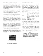
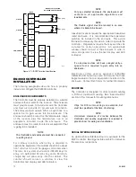
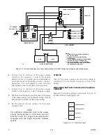
Figure 3-3—Network Extender Wiring Terminal Identification
INITIATING DEVICE CIRCUIT (IDC)
INSTALLATION
EQ22xxIDC SERIES INITIATING DEvICE CIRCUIT
(IDC)
The following paragraphs describe how to properly
install the EQ22xxIDC Initiating Device Circuit.
Mounting
The device should be securely mounted to a vibration
free surface. (See “Specifications” in this manual for
device dimensions.)
WARNING!
The hazardous area must be de-classified prior
to removing a junction box cover with power
applied.
GND
9
10
7
8
5
6
3
4
1
2
13
14
11
12
A1870
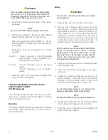
Figure 3-4—IDC Terminal Wiring Board Mounted in Six-Port
Junction Box
Wiring
1. Remove the cover from the device junction box.
2. Connect external system wiring to the appropriate
terminals on the terminal block. (See Figure 3-4
for terminal block location and Figure 3-5 for
terminal identification). The input to the IDC
consists of one or more normally open switches
(momentary pushbuttons are not recommended),
with a 10K ohm, 1/4 watt EOL resistor in parallel
across the furthest switch from the input.
IMPORTANT!
An eOL resistor must be installed on both IDC
inputs (including unused inputs). Wiring
impedance must not exceed 500 ohms.
3. Check wiring to ensure that ALL connections have
been properly made.
IMPORTANT!
Be sure that the keyed ribbon cable is properly
connected to the terminal board.
4. Inspect the junction box O-ring to be sure that it is
in good condition.
5. Lubricate the O-ring and the threads of the
junction box cover with a thin coat of grease to
ease installation and ensure a watertight
enclosure.
Summary of Contents for DET-TRONICS 95-8533
Page 128: ...7 1 95 8533 A 4 Figure A 1 System Drawing 007545 001 ...
Page 129: ...95 8533 A 5 7 1 Figure A 2 System Drawing 007545 001 ...
Page 131: ...95 8533 7 1 B 2 Figure B 1 Drawing 007546 001 ...
Page 132: ...95 8533 7 1 B 3 Figure B 2 Drawing 007546 001 ...
Page 134: ...95 8533 7 1 C 2 Figure C 1 Drawing 007547 001 ...
Page 141: ...95 8533 7 1 D 7 Figure D1 System Drawing 007545 001 ...
Page 143: ...APPENDIX E E 1 95 8533 7 1 ...

