background image

 Detector Electronics Corporation

6901 West 110th Street 

Minneapolis, MN 55438 USA

T: 952.941.5665 or 800.765.3473

F: 952.829.8750

W: http://www.det-tronics.com

E: [email protected]


X3301 Multispectrum 

IR Flame Detector

PointWatch Eclipse

®


IR Combustible Gas Detector

Eagle Quantum Premier

®


Safety System

Eagle Logic Solver 

Safety System

Det-Tronics, the DET-TRONICS logo, Eagle Quantum Premier, and Eclipse are registered trademarks or trademarks of Detector Electronics  

Corporation in the United States, other countries, or both. Other company, product, or service names may be trademarks or service marks of others.

© Copyright Detector Electronics Corporation 2009. All rights reserved.

  95-8533 

Summary of Contents for DET-TRONICS 95-8533

Page 1: ...Instructions 95 8533 Eagle Quantum Premier Fire and Gas Detection Releasing System 7 1 9 09 95 8533 ...

Page 2: ...Q22xxDCUEX Digital Communication Units 2 12 PIRECL PointWatch Eclipse 2 12 OPECL Open Path Eclipse 2 12 Section 3 Installation Safety system Design Requirements 3 1 Identifying the Area of Protection 3 1 Identifying Wiring Network LON and System Power Requirements 3 1 General Wiring Requirements 3 1 Power Wiring 3 1 Determining Power Requirements 3 3 EQ211xPS EQ213xPS and EQ217xPS Power Supplies 3...

Page 3: ...stallation 3 38 Mounting 3 38 Wiring 3 38 Configuration 3 39 intelligent protection module installation 3 40 Wiring 3 40 Configuration 3 43 Gas Detector Location and Installation 3 44 Environments and Substances that Affect Gas Detector Performance 3 44 EQ22xxDCU Digital Communication Unit used with Det Tronics H2S O2 Sensors or other Two Wire 4 20 mA Devices 3 45 Assembly and Wiring Procedure 3 4...

Page 4: ... protection module 4 15 Power Up Sequence 4 15 Embedded Logic Purpose 4 15 Embedded Logic ControlTransfer Sequence Description 4 15 Embedded Logic S3 Configurable Options 4 16 Embedded Logic Operation 4 17 EQ21xxPSM POWER SUPPLY MONITOR 4 18 eq2220GFM ground fault monitor 4 18 EQ22xxIDC series Initiating Device Circuit 4 19 EQ22xxDCU and EQ22xxDCUEX Digital communication Units 4 19 EQ25xxARM Agent...

Page 5: ...NT PARTS 5 8 DEVICE REPAIR AND RETURN 5 8 ORDERING INFORMATION 5 8 Section 6 Specifications EQ300X Controller 6 1 LON Termination Module 6 2 EQ3730EDIO Enhanced Discrete I O Module 6 3 EQ3700 DCIO Module 6 5 EQ3720 Relay Module 6 6 EQ3710AIM Analog Input Module 6 7 HART Interface Module 6 7 EQ3740IPM Intelligent Protection Module 6 8 EQ21xxPS Power Supplies 6 9 EQP2120PS B Power Supplies 6 10 Redu...

Page 6: ...r functioning of the devices under normal conditions However because of the many variations in wiring codes and regulations total compliance with these ordinances cannot be guaranteed Be certain that all wiring and equipment installation meets or exceeds the latest revisions of the appropriate NFPA Standards National Electrical Code NEC and all local ordinances If in doubt consult the Authority Ha...

Page 7: ...de manual fire alarm call boxes heat detectors and analog combustible or toxic gas measurement instruments Typical output equipment includes solenoids strobes and horns All equipment is monitored for wiring fault conditions For complete system integration the Controller has the capability to communicate with other systems such as PLCs and DCSs Different communication protocols are supported allowi...

Page 8: ...e the field devices are continuously monitoring for device based fault and alarm conditions When a fault condition occurs the Controller displays the fault condition on the Vacuum Fluorescent Text Display activates the appropriate fault LED s activates the Trouble signal using the Controller s internal enunciator and de energizes the Controller s Trouble relay CONFIGURATION PC MODBUS INTERFACE NET...

Page 9: ...nfig X X Lon Fault X X X LON Ground Fault X X Power Fail 1 X X Power Fail 2 X X RTC Fault X X Redundancy Fault X X Field Device Faults Trouble Trouble Shown onText Display LED Relay 290 Volt Fault X X AC Failed X X Battery Fault X X Beam Block X X Calibration Fault X X Channel Open X X Channel Short X X Dirty Optics X X Ground Fault Negative X X Ground Fault Positive X X IR Auto Oi Fault X X IR Fa...

Page 10: ...s have been executed will the Controller start over The Controller will start executing the first logic page of the first program at the beginning of the next logic cycle COMMUNICATION NETWORK FAULT OPERATION During normal operation the Controller is continuously broadcasting a heartbeat around the communication loop as shown in Figure 2 2 The Controller broadcasts the heartbeat in both directions...

Page 11: ...ndant controller capability User pushbutton controls reset acknowledge etc Real time system clock Internal alarm sounder Vacuum fluorescent text based display that shows current system status 8 programmable unsupervised inputs 8 programmable unsupervised relay outputs RS 485 Modbus RTU communication interface that supports coils discrete inputs and holding registers Optional ControlNet communicati...

Page 12: ...e media options EQP Supervising System EQPSS The Det Tronics EQP controllers can be supervised via the EQPSS using PCs and HMI Each EQPSS PC can communicate with up to 12 EQP controllers over an Ethernet This is a Det Tronics solution Please consult the factory for more information EQP Marine Application System For information regarding EQP Marine Application Systems refer to Appendix D LOCAL OPER...

Page 13: ...on high efficiency and high power factor An equalize switch is located on the front panel of the charger for manual activation or a multi mode electronic timer can be used for automatic activation Steady state output voltage remains within 1 2 of the setting from no load to full load for AC input voltages within 10 of the nominal input voltage EQ2220GFM Ground Fault Monitor The EQ2220GFM Ground Fa...

Page 14: ...le Specification Data sheet form number 90 1189 for additional information EQ3700 8 Channel DCIO Module The 8 Channel Discrete Input Output DCIO Module see Figure 2 10 consists of eight individually configured channels Each channel is configured as either an input or output with the appropriate wiring supervision Wiring supervision includes none open circuits and open and short circuits In additio...

Page 15: ...710AIM Analog Input Module The 8 Channel Analog Input Module see Figure 2 12 provides a means of connecting devices with a calibrated 4 20 mA output signal to the Eagle Quantum Premier System The Analog Input Module AIM provides 8 configurable channels that can be set for either combustible gas mode or universal mode The combustible gas mode provides a number of automatically programmed settings a...

Page 16: ...Agent Release Module The EQ25xxARM Series Agent Release Module ARM see Figure 2 14 provides agent release or deluge pre action capability The device is controlled by programmable logic in the Controller Time delay abort and manual release sequences allow the device output to be programmed for use in unique applications The device is field programmed to operate in one of the following modes Squib O...

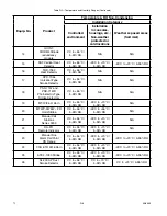
Page 17: ...rcuit conditions If a wiring fault occurs a trouble condition will be indicated at the Controller Refer to the EQ25xxSAM Specification Data sheet form number 90 1129 for additional information Figure 2 15 Signal Audible Module Table 2 7 Maximum Wiring Length for FM Approved Solenoids for Deluge and Pre Action Applications Solenoids Maximum Wire Length in Feet Meters FM Solenoid Group Manufacturer ...

Page 18: ...pere signal The device is typically connected to gas detectors where the analog signal represents the gas concentration Calibration of the DCU involves a non intrusive procedure that can be performed by one person at the device without declassifying the area The device supports two alarm setpoints that are defined as part of the device s configuration setup When detecting combustible gases the ala...

Page 19: ...ectrical wiring and electrical components IDENTIFYING WIRING NETWORK LON AND SYSTEM POWER REQUIREMENTS General Wiring Requirements WARNING DO NOT open any junction box or device enclosure when power is applied without first de classifying the hazardous area CAUTION Any deviation from the manufacturer s recommended wiring practices can compromise system operation and effectiveness ALWAYS consult th...

Page 20: ... calculate the power supply voltage for the end device calculate the voltage drops that occur due to each wire segment between the devices This involves determining the total current draw and the two conductor wire resistance per each wire segment Example Can 18 AWG wire be used to power three devices from the 24 vdc power supply Refer to the figure below for wiring and device current draw informa...

Page 21: ...2 without heater X 0 160 X3302 with heater X 0 565 X2200 X 0 135 X9800 without heater X 0 085 X9800 with heater X 0 420 X5200 without heater X 0 155 X5200 with heater X 0 490 DCUEX X 0 145 DCU with EC Sensor X 0 060 DCU with PointWatch X 0 300 DCU with DuctWatch X 0 300 Relay Module X 0 120 Analog Input Module X 0 160 Intelligent Protection Module X 0 075 EQ2220GFM X 0 018 PIRECL X 0 270 OPECL Tra...

Page 22: ...160 X3302 with heater X 0 565 X2200 X 0 135 X9800 without heater X 0 085 X9800 with heater X 0 420 X5200 without heater X 0 155 X5200 with heater X 0 490 DCUEX X 0 160 DCU with EC Sensor X 0 075 DCU with PointWatch X 0 320 DCU with DuctWatch X 0 320 Analog Input Module X 0 300 Intelligent Protection Module X 0 150 EQ2220GFM X 0 018 PIRECL X 0 275 OPECL Transmitter X 0 220 OPECL Receiver X 0 220 AR...

Page 23: ...he secure supply system that provides the secondary supply These supplies must be used in a redundant configuration where one bank of supplies are fed from the primary source and the other bank from the secondary supply Both primary and secondary supplies shall be continuously available and both rated for a minimum 100 of load Refer to Table 3 3B for power supply ratings IMPORTANT The EQP2120PS B ...

Page 24: ... X 0 083 Hours Sum of Standby and Alarm Amp Hours Multiply by 1 1 10 Safety Factor X Total Battery Amp Hour Requirement T0014A FM MINIMUM REQUIREMENT FOR EXTINGUISHING SYSTEMS IS 24 HOURS STANDBY TIME AND 5 MINUTES ALARM TIME Table 3 4 Backup Battery Requirements for Automatic Release of Extinguishing Systems Except Deluge Standby Current Standby Time Standby Amp Hours X 90 Hours Alarm Current 10 ...

Page 25: ...llation to ensure that moisture will not come in contact with electrical connections or components In applications where the network wiring is installed in conduit the use of watertight conduit seals drains breathers or equivalent is recommended to prevent damage caused by condensation within the conduit Electrostatic Discharge An electrostatic charge can build up on the skin and discharge when an...

Page 26: ...61158 2 Type A are suitable for use in LON SLC wiring For armored version contact cable manufacturer Table 3 6 Typical Specification for 16 AWG 1 5 mm2 LON Wiring Cable per Echelon Minimum Typical Maximum Units Condition DC Resistance each conductor 14 14 7 15 5 ohm km 20 C per ASTM D 4566 DC Resistance Unbalanced 5 20 C per ASTM D 4566 Mutual Capacitance 55 9 nF km per ASTM D 4566 Characteristic ...

Page 27: ...negative side of the 24 vdc power source Both terminals are connected internally 3 Connect shields to the designated shield terminals The two shield terminals are connected internally to ensure shield continuity CAUTION Do not ground either shield at the network extender enclosure Insulate the shields to prevent shorting to the device housing or to any other conductor 4 Check ALL wiring to ensure ...

Page 28: ...ve the cover from the device junction box 2 Connect external system wiring to the appropriate terminals on the terminal block See Figure 3 4 for terminal block location and Figure 3 5 for terminal identification The input to the IDC consists of one or more normally open switches momentary pushbuttons are not recommended with a 10K ohm 1 4 watt EOL resistor in parallel across the furthest switch fr...

Page 29: ...st be electrically connected to earth ground 1 Remove the enclosure cover from the device 2 Remove the communication module from the junction box Connect external wiring to the appropriate points on the device terminal block See Figure 3 4 for terminal block location and Figure 3 6 for terminal identification 3 Check wiring to ensure that ALL connections have been properly made 4 Inspect the enclo...

Page 30: ...iring caution The enclosure should be electrically connected to earth ground 1 Remove the cover from the device enclosure 2 Remove the communication module from the junction box Connect external wiring to the appropriate terminals on device terminal block See Figure 3 4 for terminal block location and Figure 3 7 for terminal identification The input to the IDCSC consists of a normally open switch ...

Page 31: ...ndow to view the Controller s text display and LED indicators Note For any selected enclosure the enclosure must conform to all applicable regulations and requirements NOTE The Trouble signal must be located in an area where it is likely to be heard Classified locations require the appropriate hazardous rated enclosure It is recommended that operators switches be installed in the enclosure This av...

Page 32: ...signal a trouble condition Shields on power cables must be connected to chassis ground earth P9 TERMINALS 57 TO 59 RS 232 S3 CONFIGURATION PORT P11 TERMINALS 63 TO 65 PORT 3 RS 232 MODBUS RTU MASTER SLAVE OR S3 CONFIGURATION P12 TERMINALS 66 TO 68 PORT 4 RS 232 MODBUS RTU MASTER SLAVE P10 TERMINALS 60 TO 62 PORT 2 RS 485 MODBUS RTU MASTER SLAVE P8 TERMINALS 54 TO 56 PORT 1 RS 485 MODBUS RTU MASTER...

Page 33: ...LENCE SUPERVISORY LOW GAS ALARM HIGH GAS ALARM INHIBIT OUTPUT INHIBIT LON FAULT BEEPER 48 49 50 51 52 53 54 55 56 57 58 59 SHIELD 1B 1A SHIELD 2B 2A P7 LON GND B A P8 RS 485 PORT 1 GND RxD TxD P9 RS 232 CONFIG PORT 60 61 62 63 64 65 66 67 68 P10 RS 485 PORT 2 TxD RxD GND A B GND P11 RS 232 PORT 3 TxD RxD GND P12 RS 232 PORT 4 P13 RS 232 HSSL Custom Connector for Redundancy Only COM 1 COM 2 DIGITAL...

Page 34: ...onnection 49 B side of signaling circuit for COM 1 50 A side of signaling circuit for COM 1 51 COM 2 shield connection 52 B side of signaling circuit for COM 2 53 A side of signaling circuit for COM 2 NOTE Refer to Figure 3 12 for location of termination jumpers Jumper P25 LON COM 1 Termination 1 2 COM 1 Terminated factory setting 2 3 COM 1 Unterminated Redundancy Jumper P26 LON COM 2 Termination ...

Page 35: ... Receive LED Green RS 232 Receive LED Green RS 485 Transmit LED Amber RS 485 Transmit LED Amber RS 485 Termination Jumper P28 RS 485 Termination Jumper P29 RS 485 Ground Fault MonitorJumper A B Channel Indicators RS 485 Receive LED Green RS 485 Receive LED Green RS 232 Transmit LED Amber RS 232 Transmit LED Amber LON COM 2 Termination Jumper LON COM 1 Termination Jumper P28 1 3 P29 1 3 P12 PORT 4 ...

Page 36: ... terminal number 62 must not be connected See Figure 3 13 for wiring details Note 1 56 7 kbps minimum and 115 2 kbps maximum baud rate required for proper communication Note 2 Consult the factory for configuration set up Note 3 Maximum SLC485 length over copper not to exceed 1000 meters Controller to Controller with Fiber Optic Link Signal Line Circuit Classification Class A or B per NFPA 72 Up to...

Page 37: ...controller configures the serial interface transmission baud rate parity check and MODBUS device address for the serial port Software selectable baud rates are 9600 19200 38400 57600 115200 and 230400 Software selectable parity is None Odd and Even The controller uses 8 data bits with 1 stop bit Port Pinout 3 position terminal block 63 TXD 64 RXD 65 GND Table 3 9 Approved Supported Media Converter...

Page 38: ...IBER OPTIC CABLE SINGLE MODE PORT 2 RS 485 A B GND 60 61 62 PORT 2 RS 485 EQP CONTROLLER No 1 60 61 62 A B GND EQP CONTROLLER No 2 PORT 2 RS 485 60 61 62 A B GND EQP CONTROLLER No 3 PORT 2 RS 485 60 61 62 A B GND EQP CONTROLLER No 4 D P D N GND BRD BTD ARD ATD ARD ATD BRD BTD Phoenix PSI MOS RS485W2 FO Phoenix PSI MOS RS485W2 FO D P D N GND FIBER OPTIC CABLE B2372 MULTI MODE TROUBLE INPUT TO EQP S...

Page 39: ...necting cable MOUNTING The controllers are designed for direct panel mounting or DIN rail mounting See Specifications section of this manual for mounting dimensions WIRING The redundant controllers are wired the same as a simplex controller except for the LON wiring and the dedicated high speed serial link which are defined below Refer to EQ300X Controller Installation for general installation det...

Page 40: ...ons when installing power supply or batteries WARNING Make sure a c power is OFF at main a c breaker before beginning power supply installation IMPORTANT Power supplies require unrestricted air flow for proper cooling MOUNTING Mount the power supply monitor in a Nationally Recognized Test Laboratory NRTL labeled enclosure Refer to the Specifications section for mounting dimensions WIRING caution T...

Page 41: ...t of the power supply and terminals 1 and 4 on J3 the AC input terminal block on the power supply monitor See Figure 3 20 J1 POWER AND LON WIRING LON ADDRESS SWITCHES J3 AC INPUT TERMINAL NO 1 YELLOW LED RED LED GREEN LED TERMINAL NO 1 TERMINAL B TERMINAL C J2 CURRENT TEST POINTS TERMINAL NO 1 SWITCH NO 1 1 1 1 1 B1949 ALARM LEVEL 1 2 3 4 200 mA O O 400 mA X O 800 mA O X 2 AMP X X X CLOSED O OPEN ...

Page 42: ... and allow the voltage to stabilize at 27 volts before closing the circuit to the battery MEASURING BATTERY VOLTAGE AND CHARGING CURRENT Measure the battery voltage at terminals 3 and 4 of terminal block J2 See Figure 3 22 1 4 C B AC BREAKER DC BREAKER H N G 24 VDC OUTPUT POWER SUPPLY MONITOR 12 11 10 9 8 7 6 5 4 3 2 1 POWER SUPPLY 12 VDC 12 VDC NRTL CABINET BATTERY CIRCUIT BREAKER POWER DIST CKT ...

Page 43: ...wer supply and module manufacturer s instruction manual provided with support documentation received with the EQP system for additional installation details and instructions WIRING caution The power supply should be properly connected to an earth ground A ground wire MUST be connected to the power supply units s ground terminal 1 Connect external wiring to the appropriate points on Power Supply Re...

Page 44: ...pply and allow the voltage to stabilize Verify the output voltage and adjust as needed Refer to EQP2120PS B Power Supplies in the Specifications section of this manual IMPORTANT The output voltage is adjustable An even current distribution must be ensured by precisely setting all power supply units that are operated in parallel to the same output voltage 10 mV IMPORTANT To ensure symmetrical curre...

Page 45: ...r COM 2 5 B side of signaling circuit for COM 2 3 6 shield connection Connector P3 Terminals 1 to 12 Terminals A B C Channels 1 to 4 Input Output Terminals Refer to individual wiring configurations for terminal descriptions Only channel 1 is shown in each diagram The information is typical for channels 2 8 CHANNEL 8 CHANNEL 7 CHANNEL 6 CLASS A CHANNEL 7 CLASS A CHANNEL 5 CLASS A CHANNEL 3 CLASS A ...

Page 46: ...wiring see Figure 3 30 Note that two channels are used for one circuit The input to the EDIO module consists of normally open switches with a 10 K ohm 1 4 watt EOL resistor in parallel across the return channel and a 3 3 K ohm 1 4 watt resistor in series with each switch NOTE If using more than one switch the first active condition switch closed must be latched Any subsequent closed switch will in...

Page 47: ...es can be connected per channel Unsupervised Output Connect external system wiring to the appropriate terminals on the terminal block See Figure 3 33 No connection should be made to Supply terminal IN OUT UNUSED OUT OUT IN IN A2283 1 R L1 L2 L1 L1 R L1 L2 L1 R L1 L2 2 3 SUPPLY A IN OUT B COMMON C EOL RESISTOR 5 K Ω A2284 1 2 3 UNUSED 3 6 7 1 2 3 6 7 1 2 3 6 7 1 2 SUPPLY A IN OUT B COMMON C EOL RES...

Page 48: ...igure 3 36 For Class A wiring refer to Figure 3 37 Note that two channels are used for one output circuit Trouble indication is provided for any open wire and the output can still be activated with a single open wire Wire one or more releasing devices to the module output No connection should be made to Supply terminal The output of the EDIO module supervises the releasing circuit via the coil of ...

Page 49: ...pplied and must be accepted by the Authority Having Jurisdiction AHJ CONFIGURATION Setting EDIO Network Address One unique network address must be assigned to each EDIO module The address is set by the 8 switch DIP assembly on the EDIO module When using the switches located on the EDIO module the address is binary coded and is the sum of all switches placed in the closed position Each discrete poi...

Page 50: ...r terminal identification Power Connector Terminals 1 to 6 24 Vdc Power Input Power connections to the DCIO depend upon the total current consumption of all the channels in the device Each output configured channel can consume up to 2 Amps The power input connection made through the terminal plug is rated to handle up to 10 Amps If the total current draw is more than 10 Amps power must be provided...

Page 51: ...90 Figure 3 39 Unsupervised Input Configuration CHANNEL 8 CHANNEL 7 CHANNEL 6 CHANNEL 5 CHANNEL 4 CHANNEL 3 CHANNEL 2 CHANNEL 1 COM 6 5 4 3 2 1 COM 2 SHLD COM 2 B COM 2 A COM 1 SHLD COM 1 B COM 1 A SHLD B A SHLD B A LON FROM PREVIOUS DEVICE LON TO NEXT DEVICE POWER 6 5 4 3 2 1 SHLD SHLD SHLD SHLD 24 VDC INPUT VOLTAGE 24 VDC INPUT VOLTAGE EQ3700DCIO TO EARTH GROUND B2097 SUPPLY A IN OUT B COMMON C ...

Page 52: ... Outputs for Open Short Circuits Connect external wiring to the appropriate terminals on the DCIO terminal block See Figure 3 42 The output of the DCIO module supervises the notification circuit by reversing the polarity of the monitoring circuit Note Polarity MUST be observed when connecting the notification device It is critical to use a notification device approved for fire alarm notification T...

Page 53: ...g device approved for use with this output module Note This type of output does not require the use of EOL resistors or diodes to supervise the circuit Note For new or retrofit installations any manufacturer s non water based agent release valves can be wired into the outputs of the ARM or DCIO modules as long as the devices utilize 24 vdc and do not exceed 2 amperes current draw Note For FM syste...

Page 54: ...r the location The enclosure must provide space to install and wire the relay module and must also provide for ground wire termination Access into the enclosure is gained by using a special tool to open the enclosure The enclosure should be rated for the temperature range of the location plus the temperature rise of all equipment installed inside the enclosure The enclosure must be rated for elect...

Page 55: ...o each relay module The address is set by the 8 switch DIP assembly on the relay module The address is binary coded and is the sum of all switches placed in the closed position Each discrete point of a relay module has a tag number and a descriptor for unique identification Det Tronics S3 Safety System Software is used for device configuration The following shows the minimum software firmware rele...

Page 56: ... local codes Connect the module power supply to terminals 1 and 2 If additional terminals are required for powering other devices these devices should be connected to terminals 4 and 5 Shields are to be connected to terminals 3 and 6 COM Connector Terminals 1 to 6 LON Terminals Be sure to observe polarity when wiring the LON 1 A side of signaling circuit for COM 1 2 B side of signaling circuit for...

Page 57: ...coded and is the sum of all switches placed in the closed position Each point of an analog input module has a tag number and a descriptor for unique identification Det Tronics S3 Safety System Software is used for device configuration The following tables show the minimum software firmware releases SUPPLY A 4 20 MA IN B COMMON C CHANNEL 1 1 2 3 A2235 SIG TRANSMITTER SUPPLY A 4 20 MA IN B COMMON C ...

Page 58: ...eld connection terminals 3 and 6 1 A side of signaling circuit for COM 1 2 B side of signaling circuit for COM 1 4 A side of signaling circuit for COM 2 5 B side of signaling circuit for COM 2 CHANNEL 8 RELEASE 2 CHANNEL 7 RELEASE 1 CHANNEL 6 BELL CHANNEL 5 ZONE 2 CHANNEL 4 ZONE 1 CHANNEL 3 SUPERVISORY CHANNEL 2 MANUAL RELEASE CHANNEL 1 ABORT COM 6 5 4 3 2 1 COM 2 SHLD COM 2 B COM 2 A COM 1 SHLD C...

Page 59: ...e input to the IPM consists of one or more normally open switches with a 10 K ohm 1 4 watt EOL resistor in parallel across the last switch No connection should be made to Supply terminal NFPA Class B Style C Three state open switch closure and short Supervised Input IDCSC Open and Short Circuit Supervision Connect external system wiring to the appropriate terminals on the terminal block See Figure...

Page 60: ...pervision is selected 2 The initiating device circuit s for use with the deluge and pre action system configuration must be wired within 20 feet and in conduit from the IPM Channel 6 Terminals 16 to 18 Unsupervised Output Connect external system wiring to the appropriate terminals on the terminal block See Figure 3 57 No connection should be made to Supply terminal IN OUT UNUSED OUT OUT IN IN A224...

Page 61: ...vice must not exceed the values shown in Table 3 15 for automatic release applications or Table 3 16 for deluge and pre action applications For solenoids this wire length includes both the wiring from the power supply to the IPM and the wiring from the module to the solenoid Note For FM system approval listing pre action and deluge applications require that only FM approved deluge valves can be wi...

Page 62: ...installations ENVIRONMENTS AND SUBSTANCES THAT AFFECT GAS DETECTOR PERFORMANCE Catalytic sensors should be located where they are safe from potential sources of contamination that can cause a decrease in the sensitivity of the device including A Substances that can clog the pores of the flame arrestor and reduce the gas diffusion rate to the sensor including Dirt and oil corrosive substances such ...

Page 63: ...a high level of combustible gas it should be calibrated at the time of exposure An additional calibration a few days later should be performed to determine whether a significant shift in sensitivity has occurred If necessary sensor should be replaced Note A combination of accessories such as rain shields and dust covers is not recommended and can result in slow response to a gas leak EQ22XXDCU DIG...

Page 64: ...nformation section for the part number of the recommended grease available from Detector Electronics If the installation uses catalytic type combustible gas sensors it is imperative that lubricants containing silicone not be used since they will cause irreversible damage to the sensor Place the cover on the enclosure Tighten only until snug Do not over tighten Sensor Separation for DCU with H2S an...

Page 65: ...mber 95 8440 or the DuctWatch instruction manual form number 95 8573 for complete installation and application information Refer to Figure 3 63 when wiring a PointWatch IR gas detector and a DCU The wiring code for PointWatch is Red 24 vdc Black common White 4 to 20 ma signal Yellow Calibration input Green Chassis ground Set the address for the device Refer to Setting Device Network Addresses for ...

Page 66: ...tighten Note If a sensor separation kit is being used attach the sensor to the separation kit junction box See Sensor Separation with DCUEX below 7 Plug the sensor into P2 on the transmitter board 8 Mount the transmitter board to the terminal wiring board and attach with the standoffs NOTE Be sure to note the correct orientation of the transmitter board If the transmitter board is rotated 180 from...

Page 67: ...e to connect P1 on the transmitter board to terminals 2 3 and 4 on the DCU terminal board See Figure 3 66 Connect the shield to the ground terminal in the DCUEX junction box 5 Connect all external wiring to the terminal wiring board inside the DCU if not already completed Re assemble the DCUEX as described in the Wiring section When completed it should look similar to the DCU as shown in Figure 3 ...

Page 68: ... P2 on the transmitter board Observe the wiring color code Connect the shield to the ground terminal in the DCUEX junction box Figure 3 66 Sensor Separation Kits Table 3 18 Maximum Separation Distances Combustible Gas Sensor to DCU Alternate Method Wire Size Maximum Separation Distance Feet Meters 18 AWG 1 0 mm2 40 12 16 AWG 1 5 mm2 60 18 14 AWG 2 5 mm2 100 30 12 AWG 4 0 mm2 150 45 Approximate Met...

Page 69: ...n terminals 3 and 4 NOTE For testing purposes a load resistor of 1200 to 1500 ohms 1 watt can be placed across terminals 1 and 4 When using an explosive initiator connect the resistor between terminals 1 and 2 and the initiator between terminals 3 and 4 as shown in Figure 3 67 CAUTION DO NOT intermix different types of initiators in release circuit Terminals 5 to 10 LON signaling circuit terminals...

Page 70: ...ST BE RATED 1 WATT MINIMUM WIRE WOUND RESISTOR PREFERRED WHEN MEASURING THE TOTAL RELEASE CIRCUIT RESISTANCE USE AN OHM METER WITH A CURRENT OUTPUT OF 10 MA MAXIMUM 3 MAXIMUM NUMBER OF EXPLOSIVE INITIATORS PER CIRCUIT IS 12 EACH CIRCUIT MUST NOT EXCEED 10 OHMS INCLUDING CABLE RESISTANCE B1900 SEE NOTE 2 Figure 3 67 Wiring Configuration for Agent Release Module Solenoids Maximum Wire Length in Feet...

Page 71: ...er is customer supplied and must be accepted by the Authority Having Jurisdiction AHJ Jumpers Terminals 13 and 14 are connected by jumper JP2 and terminals 11 and 12 are connected by jumper JP3 These two jumpers JP2 and JP3 must be cut if an auxiliary output power supply is being used See Figure 3 68 for jumper locations When an explosive initiator is being used jumper JP1 must be cut If a solenoi...

Page 72: ...aling devices it should be connected to terminals 11 and 14 Jumpers Terminals 13 and 14 are connected by jumper JP2 and terminals 11 and 12 are connected by jumper JP1 These two jumpers JP1 and JP2 must be cut if an auxiliary output power supply is being used See Figure 3 70 for jumper locations Address Setting Set device network address See Setting Device Network Addresses in this section 9 10 7 ...

Page 73: ...s are ignored NOTE The address switches in the DCIO module and relay module appear slightly different than those in other devices Refer to Figure 3 72 Example for node No 5 close rocker switches 1 and 3 binary values 1 4 for node No 25 close rocker switches 1 4 and 5 binary values 1 8 16 Note The field device sets the LON address only when power is applied to the device Therefore it is important t...

Page 74: ... VDC 2 5 24 VDC 1 4 B 5 2 A 4 1 SHIELD 6 3 COM2 COM1 SINGLE SOLENOID DUAL SOLENOIDS EQ3700DCIO SHIELD 6 3 24 VDC 5 2 24 VDC 4 1 B 5 2 A 4 1 SHIELD 6 3 COM2 COM1 P1 P2 P3 P4 IN OUT B B COMMON C C SUPPLY A A CH 1 CH 5 IN OUT B B COMMON C C SUPPLY A A CH 2 CH 6 IN OUT B B COMMON C C SUPPLY A A CH 3 CH 7 IN OUT B B COMMON C C SUPPLY A A CH 4 CH 8 CONTROLLER 24 VDC 4 2 24 VDC 3 1 B 52 49 A 53 50 TxD A ...

Page 75: ... Next allows the operator to scroll through options listed within each menu Each time the NEXT pushbutton is pushed the current options list indexes up one list item See Controller Menu Options in this section for additional information Previous allows the operator to scroll through options listed within each menu Each time the PREVIOUS pushbutton is pushed the current options list indexes down on...

Page 76: ...display through the Controller This list also includes access to options used to set system date and time and diagnostics options LED Function Status Green Power On when power is applied Red Fire Alarm On latched when any fire alarm is active Fire detected Amber Trouble On latched when a fault is detected in the system Indicates Trouble relay state Amber Ack On when the Acknowledge button is press...

Page 77: ...ncy Port Diagnostics Redundancy Info Fault Lst Flt Cntr Mode My Config Redun Mem HSSL Status Version Match Parser Comm Ack Lon Comm Msg Error Master Errors Program Flow LON A Inf LON B Inf User Logic CS App CS User Logic Config Standby Errors Program Flow LON A Inf LON B Inf User Logic CS App CS User Logic Config Power 1 Power 2 Option Bd Main Menu Display Alarms Display Devices Device Tagnames Se...

Page 78: ...e displayed Pressing the NEXT or PREVIOUS pushbuttons allows cycling through devices Pressing the CANCEL pushbutton will return the display to the Main Menu DEVICE TAG NAMES displays device tag name information for all devices on the LON loop Pressing the NEXT or PREVIOUS pushbutton allows cycling through devices Pressing the CANCEL pushbutton will return the display to the Main Menu Set Time and ...

Page 79: ...memory between controllers HSSL Status An error is generated when a problem is detected on the high speed communication link between controllers This fault is annunciated when the standby controller is offline Version Match To ensure proper redundant operation the firmware versions of redundant controllers must match This error is set when a mismatch is detected Consult the factory for firmware up...

Page 80: ...m is calculated and saved in memory Each controller is continually conducting a checksum test of the program to ensure that the data remains unchanged The application checksum fault is annunciated if the result is incorrect User Logic Many checks are conducted while the controller interprets and executes the user program The user logic error is generated if invalid or out of range data is detected...

Page 81: ...N DATA DOWNLOAD During a configuration download the controller receives configuration data that is stored into flash memory During the download process the controller halts normal operation and resets a number of controller functions Items affected and displayed during a configuration data download are listed in the following steps 1 Halt the static logic and user logic programs 2 Ignore field dev...

Page 82: ... from LON field devices 16 Configure LON field devices 17 Clear the Trouble condition 18 Text display shows a normal operation marquee message a Text display s first line indicates Det Tronics Eagle Quantum Premier b Text display s third line displays time 24 hour format and date month day year note Depending on the condition of the LON devices faults may persist for a number of minutes A and B Ca...

Page 83: ...troller and is assigned address 1 5 The controller that is connected with the secondary end of the HSSL is assigned address 2 6 If there are no faults present the primary controller defaults to the master controller and the secondary controller defaults to the standby controller 7 The master controller executes user logic and communicates with the connected LON devices 8 The standby controller ind...

Page 84: ...equests the standby to take control 4 The standby takes control and becomes the master 5 The controller indicates Device Download Active until the LON devices have been successfully updated Automatic Switchover An automatic transfer will be initiated if the master controller goes into an error self detected internal controller failure program flow error in the controller user logic checksum error ...

Page 85: ...e EDIO module displays the device s LON address by illuminating the channel active red LED LON dip switches 1 though 8 will be displayed on channels 1 through 8 When a dip switch is set to the ON position the channel active red LED will be illuminated The address is displayed for two seconds Once the address has been displayed the device s fault LED will turn off After the power up sequence the de...

Page 86: ...IO module displays the device s LON address by illuminating the channel active red LED LON dip switches 1 though 8 will be displayed on channels 1 through 8 When a dip switch is set to the ON position the channel active red LED will be illuminated The address is displayed for two seconds Once the address has been displayed the device s fault LED will turn off After the power up sequence the device...

Page 87: ...Ds have been illuminated the relay module displays the device s LON address by illuminating the channel active red LED LON dip switches 1 through 8 will be displayed on channels 1 through 8 When a dip switch is set to the ON position the channel active red LED will be illuminated The address is displayed for two seconds Once the address has been displayed the device s fault LED will turn off After...

Page 88: ...put module displays the device s LON address by illuminating the channel active red LED LON dip switches 1 through 8 will be displayed on channels 1 through 8 When a dip switch is set to the ON position the channel active red LED will be illuminated The address is displayed for two seconds Once the address has been displayed the device s fault LED will turn off After the power up sequence the devi...

Page 89: ...the channel fault amber LEDs flash ON and OFF at the same rate for all channels EMBEDDED LOGIC PURPOSE The IPM employs an Embedded logic feature that when activated during module configuration can ensure a local level of protection for the hazard during times where communication with the EQP Controller is lost or the EQP Controller is offline for repair or replacement EMBEDDED LOGIC CONTROL TRANSF...

Page 90: ...ual Release Action Delayed or Not Delayed A software selection allows the Manual Release input of the module channel 2 to be delayed or not delayed If not delayed release is immediate If delayed the signal will utilize the time delay selected for the release circuits but with a 30 second maximum Release Circuit Delay Selection A time delay is available from when the inputs channels 2 4 or 5 go act...

Page 91: ...Circuit Channel 6 Second Alarm Condition Upon receipt of an alarm from a second activated detector in the other zone Signal circuit devices are activated per the software selected signaling circuit configuration two zone mode two zones in alarm as described earlier Bell Circuit Channel 6 Programmed release time delay activated Release output s activated Manual Alarm Condition Two Zone Mode cross z...

Page 92: ... Device Status GND FLT LED Indicates Amber in the presence of a ground fault GND FLT LED Indicates Amber in the presence of a ground fault POWER LED Indicates Green when the unit is powered Table 4 15 Ground Fault Monitor Status Indicators GND FLT LED GND FLT LED PWR LED A2243 Figure 4 11 Ground Fault Monitor Status Indicator Location LED Device Status Green When On indicates power is supplied to ...

Page 93: ...hrough the window on the enclosure cover NOTE If the communication module has not been configured the red LED blinks at a 4 Hz rate NOTE The amber LED is provided for factory diagnostic purposes and is not used in the system Illumination of the amber LED normally indicates a failure in the communication chip Replacement of the communication module circuit board is required LED Device status Green ...

Page 94: ...n Blinking at a 1 Hz rate with the LED on 95 off 5 of the time indicates release and isolate Amber When On indicates a malfunction in the electronic circuitry Module replacement is required Table 4 18 Agent Release Module Status Indicators LED Device Status Green When On indicates device has power Flashes to indicate messages are being transferred over the LON Amber When On indicates a malfunction...

Page 95: ...ll cable shields are properly terminated and insulated Power wiring is installed and power source is operational Chassis ground stud must be connected to earth ground Redundant Controller The I O and LON wiring is correctly installed observing polarity All cable shields are properly terminated and insulated Power wiring is installed and power source is operational Chassis ground stud must be conne...

Page 96: ...y the system should be secured remove power from all output devices to prevent actuation 2 Check all system wiring for proper connection 3 Inspect all devices to verify that they have not been physically damaged in shipment 4 Apply power to the system NOTE To prevent the network modules from going into a fault isolation condition apply power to the EQP Controller prior to applying power to the net...

Page 97: ... the front panel provide an indication of the system status 5 Ensure configuration was performed properly 6 After any modifications have been made either to the installation or to configuration software always check the entire system for proper operation in order to ensure that the changes were performed properly STARTUP PROCEDURE for EDIO MODULE Configuration The EDIO Module is an eight channel d...

Page 98: ...on was performed properly STARTUP PROCEDURE for DCIO MODULE Configuration The DCIO Module is an eight channel device Each channel is capable of being configured as an input or output independent of any other channel Note The module is configured using Det Tronics Safety System Software Activation Time Timers are made available for output circuits only Timers are used primarily to set the timing of...

Page 99: ... then remain off 2 The output circuits should indicate the proper state for the programmed device channel active LED illuminates when the circuit is active 3 Test the entire system for proper operation to ensure that the configuration was performed properly Analog Input Module Startup 1 The Power on LED should be illuminated The Fault LED should blink once on power up then remain off 2 The input c...

Page 100: ...roperly maintain it can allow water to enter the enclosure and cause premature failure A coating of lubricant should also be applied to the threads on the cover before re assembling the enclosure This will both lubricate the cover threads and help prevent moisture from entering the enclosure caution The O rings should be lubricated with a silicone free grease The use of other lubricants is not rec...

Page 101: ...e inch above the mounting surface Do not open the junction box Hold the calibration magnet in place for approximately 4 seconds to initiate the calibration procedure CALIBRATION ALGORITHM A FOR MANUAL CALIBRATION OF UNIVERSAL DCU Normal Calibration 1 Activate the reed switch The red LED blinks while the reed switch is closed 2 After the reed switch has been closed for 3 seconds the calibrate LED b...

Page 102: ...e span value 10 The calibrate LED stays on steady 11 Remove the span gas and return the analog input to normal 12 Activate the reed switch The red LED flashes for 3 seconds while the switch is closed 13 The calibration is complete The calibrate LED turns off Note Pressing the Sensor Replacement Switch aborts calibration and starts over Note Resetting the communication module will abort the sensor ...

Page 103: ...ents to R1 when calibrating the sensor 7 Move the Calibrate Switch to the normal position 8 Activate the reed switch for 4 seconds The red LED flashes for 3 seconds while the switch is activated The communication module records the uncalibrated value in position one of the calibration log and calibrates the zero value The calibrate LED goes on steady 9 Move the Calibration Switch to the calibrate ...

Page 104: ... least 4 seconds The red LED flashes for 3 seconds while the switch is closed 3 The calibrate LED flashes indicating calibration has begun 4 The communication module waits 3 seconds 5 The communication module records the uncalibrated value in the calibration log and calibrates the span value 6 The calibrate LED stays on steady 7 The communication module waits 3 seconds 8 Calibration is complete Th...

Page 105: ...n module for approxImately 1 second Note Allow at least 10 minutes for the sensor to warm up Note Pressing the Sensor Replacement Switch prevents the communication module from generating a fault signal when the input drops to zero Note The calibration will not be aborted if the calibration procedure is not completed within 12 minutes 2 Apply zero gas 3 The calibrate LED flashes indicating that it ...

Page 106: ...ty output wiring When output should be energized measure contact command User logic resistance using an ohm meter Verify that wiring from output is not open Using EQ Safety System Software verify that logic is trying to operate the channel Serial links are not responding Faulty wiring Check that P8 and P9 are fully inserted Incorrect serial link Verify that communication LEDs are flashing configur...

Page 107: ...ortation prepaid to the factory in Minneapolis ORDERING INFORMATION When ordering please specify Power Supplies Part Number Description 006979 001 EQ21xxPSM Power Supply Monitor 000604 013 EQ2110PS Power Supply 10A 60 Hz 000604 014 EQ2130PS Power Supply 30A 60 Hz 000604 015 EQ2175PS Power Supply 75A 60 Hz 000604 034 EQ2111PS Power Supply 10A 50 Hz 000604 035 EQ2131PS Power Supply 30A 50 Hz 000604 ...

Page 108: ...CE IPM Matrix MODEL DESCRIPTION EQ3740 8 Channel Intelligent Protection Module TYPE MOUNTING OPTION D Din Rail P Panel TYPE APPROVAL AGENCY W FM CSA ATEX CE Component certification Controller Communication Cables Length Part No Description 15 ft 30 ft 50 ft 4 57 m 9 14 m 15 24 m 007633 001 Controller RS 232 Cable X DB9 Female PC Connection 007633 002 Controller RS 232 Cable X DB9 Female PC Connect...

Page 109: ...FL 226166 009 Methane 35 LFL REPLACEMENT PARTS FOR CALIBRATION KIT Part Number Description 162552 001 Regulator 101678 007 3 foot hose 004976 001 Standard calibration cup 225777 001 Calibration cup for sensor separation H2S CALIBRATION KIT 227115 001 H2S Calibration Kit for electro chemical sensors only includes regulator hose calibration cup and two cylinders of calibration gas REPLACEMENT PARTS ...

Page 110: ...Configurable for normally energized or de energized de energized is the default mode Unsupervised Inputs Two State input on off User selectable normally open or normally closed contact N O is the default Trouble Output SPDT normally open normally closed contact Non Configurable normally energized only TEMPERATURE RANGE Operating 40 F to 185 F 40 C to 85 C Storage 40 F to 185 F 40 C to 85 C Excludi...

Page 111: ...ate Cancel Enter Next Previous Reset Acknowledge Silence DET TRONICS EAGLE QUANTUM PREMIER Safety System Controller Fire Alarm Inhibit Power Supr High Gas Trouble Cntrl Flt Lon Fault Low Gas Ack Silence Out Inhibit Eagle Quantum Premier Time Date Cancel Enter Next Previous Reset Acknowledge Silence DET TRONICS G2103 10 75 27 3 8 2 20 8 6 7 17 0 5 95 15 1 DIMENSIONS OF PANEL MOUNT CONTROLLER WITH O...

Page 112: ...s certification FM CSA Class I Div 2 Groups A B C D T4 Class I Zone 2 Group IIC T4 CENELEC ATEX FM II 3 G EEx nC IIC T4 DEMKO 05 ATEX 138864U T4 Tamb 40 C to 85 C Special conditions for safe use The device shall be installed in an enclosure that complies with all relevant requirements of EN 50021 1999 and provides a degree of ingress protection of at least IP54 The device may only be installed con...

Page 113: ...ge Vout Vin 1 Vdc OUTPUT STYLE Form A normally off RESPONSE TIME Output actuates in 0 15 second after acknowledging an alarm command message SUPERVISED OUTPUT RATING Signaling Type Style Y MAXIMUM OUTPUT CURRENT Per Channel 2 amperes at 30 Vdc maximum Automatic short circuit protection provided Instantaneous short circuit current 15 amperes SUPERVISORY CURRENT Per Channel Reverse current monitored...

Page 114: ...A Approval details CENELEC CE ATEX EMC Directive Compliant 0539 FM II 3 G EEx nC IIC T4 DEMKO 02 ATEX 133864U T4 Tamb 40 C to 85 C Refer to Appendix C for CE Mark details Special conditions for safe use The device shall be installed in an enclosure that complies with all relevant requirements of EN 50021 1999 and provides a degree of ingress protection of at least IP54 The device may only be insta...

Page 115: ...ER REQUIREMENTS 3 watts nominal 4 watts maximum INPUT VOLTAGE 24 vdc nominal 18 to 30 vdc 10 overvoltage will not cause damage to the equipment relay contacts 30 VDC 2 amps resistive 125 VAC 0 5 amp resistive FM and CSA only LON communication Digital communication transformer isolated 78 5 kbps TEMPERATURE RANGE Operating 40 F to 185 F 40 C to 85 C Storage 67 F to 185 F 55 C to 85 C HUMIDITY RANGE...

Page 116: ...tions for safe use The device shall be installed in an enclosure that complies with all relevant requirements of EN 50021 1999 and provides a degree of ingress protection of at least IP54 The device may only be installed connected or removed when the area is known to be non hazardous Refer to Appendix D for USCG Approval details HART INTERFACE MODULE HIM INPUT VOLTAGE 24 vdc nominal 18 to 30 vdc 1...

Page 117: ...en the area is known to be non hazardous INPUT INITIATING DEVICE CIRCUITS CONTACT MONITOR TYPE channel 1 3 NOTE An input must be active for at least 750 milliseconds in order to be recognized UNSUPERVISED INPUT Two state input on off Normally open contact No EOL resistor required SUPERVISED INPUT CLASS B STYLE B Two state input active trouble End of Line Resistor 10 K ohms 20 Open Circuit 45 K ohm...

Page 118: ...PUT TYPES Configurable for device applications Continuous Timed EQ21XXPS POWER SUPPLIES INPUT VOLTAGE Selectable for 120 208 or 240 vac input power 10 INPUT CURRENT 60 Hz Models EQ2110PS 4 amps at 120 VAC EQ2130PS 11 6 6 amps at 120 208 240 VAC EQ2175PS 24 15 12 amps at 120 208 240 VAC 50 Hz Models EQ2111PS 4 amps at 120 VAC EQ2131PS 6 amps at 240 VAC EQ2176PS 12 amps at 240 VAC OUTPUT CURRENT EQ2...

Page 119: ...tion FM CSA Ordinary locations Refer to Appendix D for USCG Approval details REDUNDANCY MODULE QUINT DIODE 40 Temperature Range Operating 32 F to 122 F 0 C to 50 C Marine Applications 32 F to 131 F 0 C to 55 C Storage 40 F to 185 F 40 C to 85 C Humidity Range 5 to 95 RH non condensing Dimensions in Inches Centimeters Width Height Depth 2 4 6 2 4 10 2 3 3 8 4 EQ21XXPSM POWER SUPPLY MONITOR INPUT VO...

Page 120: ...s I Div 1 Groups B C D Class I Zone 1 Group IIC Class II III Div 1 Groups E F G Class I Div 2 Groups A B C D T4A Class I Zone 2 Group IIC T4 Class II III Div 2 Groups F G T4A NEMA Type 4X Refer to Appendix A for FM Approval details Refer to Appendix B for CSA Approval details CENELEC CE ATEX EMC Directive Compliant 0539 FM II 2 G EEx d IIC T4 T6 DEMKO 02 ATEX 131321X T6 Tamb 55 C to 50 C T5 Tamb 5...

Page 121: ... overvoltage will not cause damage to the equipment POWER CONSUMPTION DCU with toxic gas sensor transmitter 95 ma max DCU with transmitter and combustible gas sensor 180 ma maximum during normal operation 500 ma during startup INPUTS 4 to 20 ma analog signal Non intrusive calibration OUTPUTS Digital communication transformer isolated 78 5 kbps TEMPERATURE RANGE Operating 40 F to 167 F 40 C to 75 C...

Page 122: ...4X Refer to Appendix A for FM Approval details Refer to Appendix B for CSA Approval details CENELEC CE ATEX EMC Directive Compliant 0539 FM II 2 G EEx d IIC T4 T6 DEMKO 02 ATEX 131321X T6 Tamb 55 C to 50 C T5 Tamb 55 C to 65 C T4 Tamb 55 C to 75 C IP66 Special Conditions for Safe Use X The device has an ambient temperature rating for performance of 40 C to 75 C Refer to Appendix C for CE Mark deta...

Page 123: ...gital transformer isolated 78 5k Baud TEMPERATURE RANGE Operating 40 F to 167 F 40 C to 75 C Storage 67 F to 185 F 55 C to 85 C HUMIDITY 5 to 95 RH at 70 C DIMENSIONS See Figure 6 7 Certification FM CSA Class I Div 1 Groups B C D Class I Zone 1 Group IIC Class II III Div 1 Groups E F G Class I Div 2 Groups A B C D T4A Class I Zone 2 Group IIC T4 Class II III Div 2 Groups F G T4A NEMA Type 4X Refer...

Page 124: ...iency high power factor and short circuit protection These chargers provide separate adjustable voltages for floating or equalizing lead or nickel cadmium cells An equalize switch is located on the front panel of the charger for manual activation or a multi mode electronic timer can be used for automatic activation Steady state output voltage remains within 1 2 of the setting from no load to full ...

Page 125: ...ance verified 0 to 20 50 or 100 ppm per FM requirements Accuracy 2 ppm from 0 to 20 ppm 10 of concentration from 21 to 100 ppm Models C7064E4012 and C7064E5012 Hydrogen Sulfide H2S Sensors Explosion proof for Class I Div 1 Groups C and D Hazardous Classified Locations per FM 3615 Model C7064E5014 Hydrogen Sulfide H2S Sensors Explosion proof for Class I Div 1 Groups B C and D Hazardous Classified L...

Page 126: ...er Relay Output Unsupervised per ANSI NFPA 72 Cl 1 5 8 Exception 7 8 Controller Trouble Relay Output Unsupervised per ANSI NFPA 72 Cl 1 5 8 Exception 7 8 Controller 232 Expansion Output SIL or Non SIL Unsupervised per ANSI NFPA 72 Cl 1 5 8 Exception 7 8 Controller SLC485 Expansion Output including Class B Style 4 Single Channel Single Mode Fiber optional fiber optic equipment SIL or Non SIL Class ...

Page 127: ... B Style Y Supervised Solenoids Single open or ground fault per ANSI NFPA 72 Cl 1 5 8 Group B ASCO T8210A107 Group D ASCO 8210G207 Group E Skinner 73218BN4UNLVNOC111C2 Group F Skinner 73212BN4TNLVNOC322C2 Group G Skinner 71395SN2ENJ1NOH111C2 Group H Viking HV 274 060 7 Analog Input Module Initiating Device Circuit IDC Class B Style B IDC Input Initiating Device Circuit IDC Class B Style B IDCGF In...

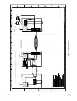
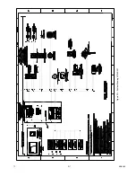
Page 128: ...7 1 95 8533 A 4 Figure A 1 System Drawing 007545 001 ...

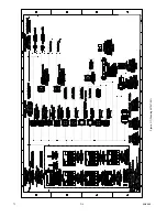
Page 129: ...95 8533 A 5 7 1 Figure A 2 System Drawing 007545 001 ...

Page 130: ...n of the devices has been CSA verified using the respective EQ22xxDCU EQ22xxDCUEX and PIRECL Series with the Det Tronics 225130 001 50 LFL methane and 227115 001 H2S Calibration Kits The EQ22xxDCU Series can be used with any CSA Certified 4 20 ma device NOTE CSA Certification of the 4 20 ma input does not include or imply approval of the gas detection apparatus such as sensors transmitters or devi...

Page 131: ...95 8533 7 1 B 2 Figure B 1 Drawing 007546 001 ...

Page 132: ...95 8533 7 1 B 3 Figure B 2 Drawing 007546 001 ...

Page 133: ... wire shields to the shield connections on the terminal blocks or to the earth ground on the case For installations without conduit use double shielded cable Terminate the outer shield to the earth ground on the case Terminate the inner shield to the shield connection on the terminal blocks ATEX Directive The Eagle Quantum Premier Fire and Gas Detection Releasing System was tested and certified to...

Page 134: ...95 8533 7 1 C 2 Figure C 1 Drawing 007547 001 ...

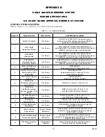
Page 135: ...Aluminum 6 SS 6 EQ22xxDCUEX Digital Communication Unit Combustible Det Tronics EQ225 6 3DCUEX Enclosure material 5 Aluminum 6 SS Uses CGS Gas Sensor 7 CGS Combustible Gas Sensor Det Tronics CGSS1A6C2R1X Used with the EQ22xxDCUEX 8 PIRECLAx4 PointWatch Hydrocarbon Gas Detector Det Tronics PIRECLA 1 4 A B 1 2 W T 1 2 9 PIRECLAx4 PointWatch Hydrocar bon Gas Detector Duct Mount Det Tronics PIRECLA 1 4...

Page 136: ...ector Air Products Controls SL 2000 P installed in Hoffman LWC204015SS6 NEMA 4X enclosure uses Apollo 55000 328A photoelectric head w RW 268A base Table D 1 List of Approved Equipment Continued IMPORTANT The EQP2120PS B Power Supplies provide EQP System devices with power from input supply 120 to 220 V ac The EQP2120PS B Power Supplies are used in pairs where primary source of input supply is conn...

Page 137: ... for some components and an increase in the rating range for other components with respect to that specified by their manufacturers The manufacturer s published operating temperature and relative humidity specifications may be viewed as reference only INSTALLATION The EQP2120PS B Power Supply and Diode Redundancy Module are Panel mounted and intended to be mounted within the same cabinet as the EQ...

Page 138: ...40AC 24DC 20 Panel Mount 009934 001 Diode Redundancy Module Phoenix Contact QUINT DIODE 40 Panel Mount 007609 269 EQ3001PCSW C EQP System Controller panel mount 009931 001 Q900C1001 Duct Mount Kit For other USCG Approved EQP System components refer to Table D 1 or contact Det Tronics Customer Service Refer to Section 3 of this manual for determining power requirements ...

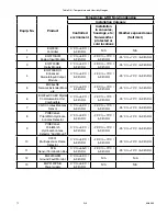
Page 139: ...70 C 5 95 RH 25 C to 70 C 5 95 RH 6 EQ22xxDCUEX Digital Communication Unit Combustible 0 C to 55 C 5 95 RH 25 C to 70 C 5 95 RH 25 C to 70 C 5 95 RH 7 CGS Combustible Gas Sensor 0 C to 55 C 5 95 RH 25 C to 70 C 5 95 RH 25 C to 70 C 5 95 RH 8 PIRECLAx4 PointWatch Hydrocar bon Gas Detector 0 C to 55 C 5 95 RH 25 C to 70 C 5 95 RH 25 C to 70 C 5 95 RH 9 PIRECLAx4 PointWatch Hydrocarbon Gas Detector D...

Page 140: ... Smoke Detectors 0 C to 55 C 5 95 RH N A N A 19 MT 12 24 R Horn 0 C to 55 C 5 95 RH 25 C to 70 C 5 95 RH N A 20 MTWP 2475W FR Horn Strobe 0 C to 55 C 5 95 RH 25 C to 55 C 5 95 RH N A 21 Manual Call Stations Series 3300 0 C to 55 C 5 95 RH 25 C to 70 C 5 95 RH N A 22 RA 911 Remote Indicator 0 C to 55 C 5 95 RH 25 C to 70 C 5 95 RH N A 23 Manual Fire Alarm Call Point PB Range 0 C to 55 C 5 95 RH 25 ...

Page 141: ...95 8533 7 1 D 7 Figure D1 System Drawing 007545 001 ...

Page 142: ...e Monitoring up to 16 Power Supplies TO EDIO L N DC OK 13 14 PS n PHOENIX QUINT PS 100 240AC 24DC 20A L N DC OK 13 14 PS 1 PHOENIX QUINT PS 100 240AC 24DC 20A L N DC OK 13 14 PS PHOENIX QUINT PS 100 240AC 24DC 20A L N DC OK 13 14 PS PHOENIX QUINT PS 100 240AC 24DC 20A B2438 ...

Page 143: ...APPENDIX E E 1 95 8533 7 1 ...

Page 144: ... X X O O O O X O 68 O O X O O O X O 69 X O X O O O X O 70 O X X O O O X O Node Rocker Switch Address 1 2 3 4 5 6 7 8 71 X X X O O O X O 72 O O O X O O X O 73 X O O X O O X O 74 O X O X O O X O 75 X X O X O O X O 76 O O X X O O X O 77 X O X X O O X O 78 O X X X O O X O 79 X X X X O O X O 80 O O O O X O X O 81 X O O O X O X O 82 O X O O X O X O 83 X X O O X O X O 84 O O X O X O X O 85 X O X O X O X ...

Page 145: ...90 O X X X X X O X 191 X X X X X X O X 192 O O O O O O X X 193 X O O O O O X X 194 O X O O O O X X 195 X X O O O O X X 196 O O X O O O X X 197 X O X O O O X X 198 O X X O O O X X 199 X X X O O O X X 200 O O O X O O X X 201 X O O X O O X X 202 O X O X O O X X 203 X X O X O O X X 204 O O X X O O X X 205 X O X X O O X X 206 O X X X O O X X 207 X X X X O O X X 208 O O O O X O X X 209 X O O O X O X X 2...

Page 146: ...IR Combustible Gas Detector Eagle Quantum Premier Safety System Eagle Logic Solver Safety System Det Tronics the DET TRONICS logo Eagle Quantum Premier and Eclipse are registered trademarks or trademarks of Detector Electronics Corporation in the United States other countries or both Other company product or service names may be trademarks or service marks of others Copyright Detector Electronics ...

Reviews: