7.1
95-8533
2-8
EQ3730EDio Enhanced Discrete input/output module
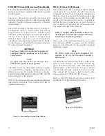
The 8 Channel EDIO Module (see Figure 2-9) expands
the Input and Output capability of the Eagle Quantum
Premier System.
The unit is designed to provide continuous and
automated fire/gas protection, while ensuring system
operation through continuous supervision of System
Inputs/Outputs.
The EDIO module provides eight channels of
configurable input or output points that can be
programmed for supervised or unsupervised
operation. Each input point can accept fire detection
devices such as heat, smoke, or unitized flame
detectors. Each output point can be configured for
signaling or releasing output operation. Each channel
on the module is provided with individual indicators
for active and fault conditions.
important
For Class A wiring, two input/output channels are
combined, thereby supporting up to four input/
output circuits.
note
An input must be active for at least 750
milliseconds in order to be recognized.
The EDIO module can be mounted directly to a panel,
or it can be DIN rail mounted. System status can be
determined using the trouble-shooting procedures,
Eagle Quantum Safety System Software (S3) and the
status indicators on the module.
Refer to the Enhanced Discrete Input/Output Module
Specification Data sheet (form number 90-1189) for
additional information.
EQ3700 8 Channel DCio module
The 8 Channel Discrete Input/Output (DCIO) Module
(see Figure 2-10) consists of eight individually
configured channels. Each channel is configured as
either an input or output with the appropriate wiring
supervision. Wiring supervision includes none, open
circuits, and "open and short" circuits. In addition to
defining the type of supervision, an input channel is
also configured to generate the appropriate static
logic alarm message to the controller.
note
nFPA 72 requires wire supervision selection for
fire detection and notification devices (IDC, nAC,
supervisory and releasing devices).
Heat, smoke, or unitized flame detectors can be wired
into channels defined as inputs. Horns, strobes/
beacons, and solenoids can be wired into channels
defined as outputs.
note
the DCIo outputs only support equipment that
operates on 24 vdc (not to exceed 2 amperes
per channel).
The DCIO has two device status LEDs, as well as two
LEDs for each channel. On the device level, one
green LED indicates power, while the other amber
LED indicates a LON CPU fault. For each channel,
one red LED indicates channel activation and the
other amber LED indicates a fault condition when
wiring supervision is defined for the channel.
Refer to the DCIO Specification Data sheet (form
number 90-1149) for additional information.
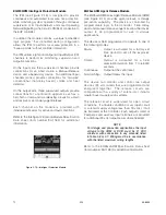
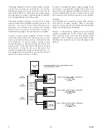
Figure 2-10—DCIO Module
Figure 2-9—Enhanced Discrete Input/Output Module
Summary of Contents for DET-TRONICS 95-8533
Page 128: ...7 1 95 8533 A 4 Figure A 1 System Drawing 007545 001 ...
Page 129: ...95 8533 A 5 7 1 Figure A 2 System Drawing 007545 001 ...
Page 131: ...95 8533 7 1 B 2 Figure B 1 Drawing 007546 001 ...
Page 132: ...95 8533 7 1 B 3 Figure B 2 Drawing 007546 001 ...
Page 134: ...95 8533 7 1 C 2 Figure C 1 Drawing 007547 001 ...
Page 141: ...95 8533 7 1 D 7 Figure D1 System Drawing 007545 001 ...
Page 143: ...APPENDIX E E 1 95 8533 7 1 ...

