3-27
7.1
95-8533
ENHANCED DISCRETE INPUT/
OUTPUT (EDIO) MODULE
INSTALLATION
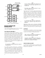
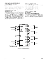
All electrical connections are made to the field wiring
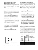
connectors furnished with the module. Refer to Figure
3-25 for identification of module wiring terminals.
Connector P1, Terminals 1 to 6
24 vdc Power Input
Connect the module power supply to terminals 1 and
2. If additional terminals are required for powering
other devices, these devices should be connected to
terminals 4 and 5. Shields are to be connected to
terminals 3 and 6 — chassis (earth) ground terminals.
Terminals are rated for 10 amperes. Use both sets of
input terminals in parallel if total output current can
exceed 10 amperes.
Connector P2, Terminals 1 to 6
LON/SLC Signaling Circuit Terminals
Be sure to observe polarity when wiring the LON/SLC.
1 — "A" side of signaling circuit for COM 1
2 — "B" side of signaling circuit for COM 1
4 — "A" side of signaling circuit for COM 2
5 — "B" side of signaling circuit for COM 2
3, 6 — shield connection
Connector P3, Terminals 1 to 12
Terminals A,B & C
Channels 1 to 4 Input / Output Terminals
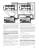
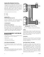
Refer to individual wiring configurations for terminal
descriptions. Only channel 1 is shown in each
diagram. The information is typical for channels 2-8.
CHANNEL 8
CHANNEL 7
CHANNEL 6
CLASS A
CHANNEL 7
CLASS A
CHANNEL 5
CLASS A
CHANNEL 3
CLASS A
CHANNEL 1
CHANNEL 5
CHANNEL 4
CHANNEL 3
CHANNEL 2
CHANNEL 1
COM
6
5
4
3
2
1
COM 2 SHLD
COM 2 B
COM 2 A
COM 1 SHLD
COM 1 B
COM 1 A
SHLD
B
A
SHLD
B
A
LON FROM
PREVIOUS DEVICE
LON TO
NEXT DEVICE
POWER
6
5
4
3
2
1
SHLD
–
+
SHLD
–
+
SHLD
*
–
+
SHLD
*
–
+
24 VDC
INPUT VOLTAGE
24 VDC
INPUT VOLTAGE
EQ3730EDIO
TO
EARTH
GROUND
A2287
+ SUPPLY A
IN–/OUT+ B
COMMON C
+ SUPPLY A
IN–/OUT+ B
COMMON C
+ SUPPLY A
IN–/OUT+ B
COMMON C
+ SUPPLY A
IN–/OUT+ B
COMMON C
+ SUPPLY A
IN–/OUT+ B
COMMON C
+ SUPPLY A
IN–/OUT+ B
COMMON C
+ SUPPLY A
IN–/OUT+ B
COMMON C
+ SUPPLY A
IN–/OUT+ B
COMMON C
1
2
3
4
5
6
7
8
9
10
11
12
13
14
15
16
17
18
19
20
21
22
23
24
*
SHIELDS ON POWER WIRES ARE OPTIONAL
UNLESS REQUIRED BY LOCAL CODES.
Figure 3-25—EDIO Module Wiring Terminals
Summary of Contents for DET-TRONICS 95-8533
Page 128: ...7 1 95 8533 A 4 Figure A 1 System Drawing 007545 001 ...
Page 129: ...95 8533 A 5 7 1 Figure A 2 System Drawing 007545 001 ...
Page 131: ...95 8533 7 1 B 2 Figure B 1 Drawing 007546 001 ...
Page 132: ...95 8533 7 1 B 3 Figure B 2 Drawing 007546 001 ...
Page 134: ...95 8533 7 1 C 2 Figure C 1 Drawing 007547 001 ...
Page 141: ...95 8533 7 1 D 7 Figure D1 System Drawing 007545 001 ...
Page 143: ...APPENDIX E E 1 95 8533 7 1 ...

