109
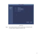
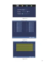
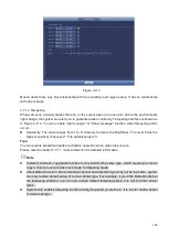
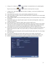
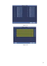
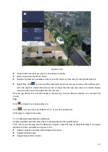
Figure 3-114
3.7.1.3 Video Loss
After connected the system to the remote device, system can generate an alarm once the remote
device has lost the video. System can trigger the corresponding alarm operations.
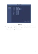
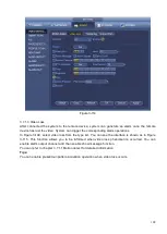
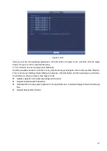
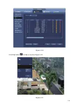
In Figure 3-109, select video loss from the type list. You can see the interface is shown as in Figure
3-115. This function allows you to be informed when video loss phenomenon occurred. You can
enable alarm output channel and then enable show message function.
You can refer to chapter 3.7.1.1Motion detect for detailed information.
Tips:
You can enable preset/tour/pattern activation operation when video loss occurs.
Summary of Contents for EmPower NVR
Page 1: ...EmPower NVR User s Manual V4 4 3...
Page 36: ...23 Figure 3 16 Step 2 Click device display edit interface See Figure 3 17...
Page 97: ...84 Figure 3 91 Figure 3 92...
Page 120: ...107 Figure 3 110 Figure 3 111 Figure 3 112...
Page 131: ...118 Figure 3 123 Figure 3 124...
Page 133: ...120 Figure 3 126 Click draw button to draw the zone See Figure 3 127...
Page 137: ...124 Figure 3 130 Click Draw button to draw a zone See Figure 3 131 Figure 3 131...
Page 142: ...129 Figure 3 136 Click draw button to draw the zone See Figure 3 137...
Page 155: ...142 Figure 3 149 Figure 3 150...
Page 156: ...143 Figure 3 151 Figure 3 152...
Page 174: ...161 Figure 3 172 Figure 3 173...
Page 277: ...264 Figure 4 61 Figure 4 62 Figure 4 63...
Page 303: ...290 Figure 4 101 Figure 4 102...
Page 327: ...314 Figure 4 136 Note For admin you can change the email information See Figure 4 137...

