28
The DE0-Nano Control Panel can be used to light up LEDs, change the buttons/switches status,
read/write to SDRAM Memory, read ADC channels, and display the Accelerometer information.
4
4
.
.
2
2
C
C
o
o
n
n
t
t
r
r
o
o
l
l
l
l
i
i
n
n
g
g
t
t
h
h
e
e
L
L
E
E
D
D
s
s
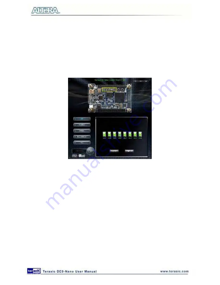
A simple function of the Control Panel is to allow setting the values displayed on LEDs. Choosing
the
LED
tab displays the window in
Figure 4-3
. Here, you can directly turn the LEDs on or off
individually or by clicking “Light All” or “Unlight All”.
Figure 4-3 Controlling LEDs
4
4
.
.
3
3
S
S
w
w
i
i
t
t
c
c
h
h
e
e
s
s
a
a
n
n
d
d
P
P
u
u
s
s
h
h
b
b
u
u
t
t
t
t
o
o
n
n
s
s
Choosing the
Switches
tab displays the window in
Figure 4-4
. The function is designed to monitor
the status of slide switches and pushbuttons in real time and show the status in a graphical user
interface. It can be used to verify the functionality of the slide switches and pushbuttons.
Summary of Contents for De0-Nano
Page 1: ...1 ...
Page 4: ...4 9 3 Revision History 155 9 4 Copyright Statement 155 ...
Page 44: ...44 Figure 6 5 Browse to find the location Figure 6 6 There is no need to test the driver ...
Page 90: ...90 Figure 7 14 Add NIOS II Processor ...
Page 93: ...93 Figure 7 17 Rename the CPU 1 Figure 7 18 Rename the CPU 2 ...
Page 98: ...98 Figure 7 23 Add On Chip Memory ...
Page 100: ...100 Figure 7 25 Update Total memory size ...
Page 102: ...102 Figure 7 28 Update CPU settings ...
Page 104: ...104 Figure 7 30 Add PIO ...
Page 106: ...106 Figure 7 32 PIO 21 Rename pio_0 to pio_led as shown in Figure 7 33 Figure 7 33 Rename PIO ...
Page 113: ...113 Figure 7 43 Input verilog Text Figure 7 44 Open DE0_NANO_SOPC v ...
Page 146: ...146 Figure 8 16 Display Progress and Result Information for the SDRAM Demonstration ...
Page 150: ...150 Figure 9 3 Select Devices Page ...
Page 151: ...151 Figure 9 4 Convert Programming Files Page ...


