


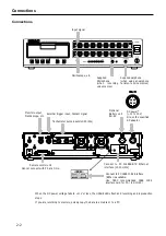


Names and Parts
1-11
1 FG
terminal
Connects the grounding wire.
2 MON OUT connector
Outputs in analog format, the signal of a channel during recording-standby status, recording, or reproduction.
You use the supplied LX Navi software to select the channel you want to monitor. You can set the output
range in 0.1 V steps, from 1 V to 5 V. The same filter as for the output amp is applied to this monitor
output.
Outputs the generator output signal at the LX-20/20L.
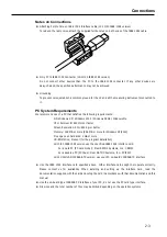
3 EXT TRIGGER IN connector
Inputs the trigger signal when using an external contact signal as the trigger to start recording.
4 Cooling
fan
Exhaust fans used for cooling the main unit. Do not cover the outlet vent.
5 BU-80
connector
Uses to connect the optional battery unit.
6 DC IN connector
Inputs power in the range from +11 to 30 V.
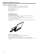
7 IEEE 1394 connector (LX-10/20 IEEE 1394 version)
Connects to a PC. Use a recommended interface card on the PC.
100BASE-TX connector (LX-10L/20L LAN version)
Connects to a PC. LED located side of the connector flashes while communications.
8 DIGITAL CONTROL connector
Use when using a contact signal to control recording or reproduction.
9 PULSE IN A/B connector (LX-20/20L version)
Connects tachometer pulse inputs.
Summary of Contents for LX Series
Page 2: ......
Page 10: ...Contents viii...
Page 26: ...Sampling Frequency and Number of Channels 1 16...
Page 117: ...Main Unit Specifications 6 3 External Dimensions...
Page 142: ...Recording Synchronization Specifications 6 28...
Page 146: ...Note 7 4 Note...
Page 147: ......