background image

NICE3000

new

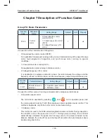
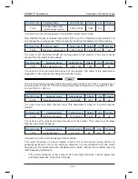
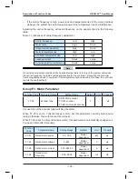
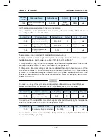
 User Manual                                                                                         Function Code Table

- 131 -

Function 

Code

Parameter Name

Setting Range

Default

Unit

Property

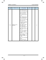
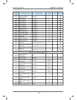
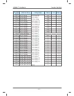
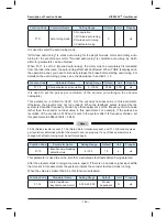
FE-07

Floor 7 display

17: Display "R"
18: Display "-"

19: No display 

20: Display "12"
21: Display "13"
22: Display "23"
23: Display "C"
24: Display "D"
25: Display "E"
26: Display "F"
27: Display "I"
28: Display "J"
29: Display "K"
30: Display "N"
31: Display "O"
32: Display "Q"
33: Display "S"
34: Display "T"
35: Display "U"
36: Display "V"
37: Display "W"
38: Display "X"
39: Display "Y"
40: Display "Z"
41: Display "15"
42: Display "17"
43: Display "19"

(End)

1907

-

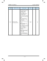
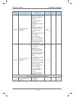
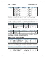
FE-08

Floor 8 display

1908

-

FE-09

Floor 9 display

1909

-

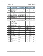
FE-10

Floor 10 display

0100

-

FE-11

Floor 11 display

0101

-

FE-12

Floor 12 display

0102

-

FE-13

Floor 13 display

0103

-

FE-14

Floor 14 display

0104

-

FE-15

Floor 15 display

0105

-

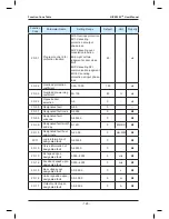
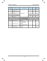
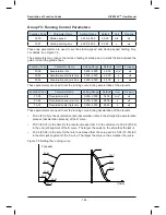
Floor 16 to floor 30 display

FE-31

Floor 31 display

0301

-

FE-35

Floor 32 display

0

-

FE-36

Floor 33 display

0

-

FE-37

Floor 34 display

0

-

FE-38

Floor 35 display

0

-

FE-39

Floor 36 display

0

-

FE-40

Floor 37 display

0

-

FE-41

Floor 38 display

0

-

FE-42

Floor 39 display

0

-

FE-43

Floor 40 display

0

-

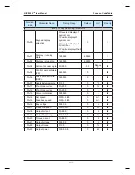
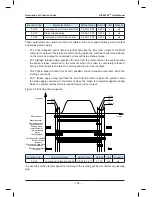
FE-52

Highest digit selection 1

0

-

FE-53

Highest digit selection 2

0

-

FE-54

Highest digit selection 3

0

-

FE-55

Highest digit selection 4

0

-

FE-56

Highest digit selection 5

0

-

Summary of Contents for NICE3000 New

Page 1: ......

Page 2: ...nce office buildings shopping centers and hospitals This manual describes the correct use of the NICE3000new including product features safety information and precautions installation parameter setting commissioning and maintenance inspection Read and understand the manual before using the product and keep it carefully for future maintenance The personnel who involve in system installation commiss...

Page 3: ... x CANbus Modbus 1 x Modbus 1 x Modbus Motor driving type Separate control for synchronous and asynchronous motors Integrated control for synchronous and asynchronous motors No load cell startup Supporting SIN COS encoder only Supporting Push pull encoder Open collector incremental encoder UVW encoder SIN COS encoder Endat encoder Control mode Sensorless flux vector control SFVC Closed loop vector...

Page 4: ...on To guarantee safety use an electromagnetic contactor Do not use it to start or stop the controller because such operation reduces the service life of the controller Suppress the high order harmonic to improve the power factor Reduce the electromagnetic interference on the input side Reliably ground the motor and the controller to prevent electric shock Do not install the capacitor or surge supp...

Page 5: ...vator opens the door This function is invalid in fire emergency state Auxiliary operation box An optional auxiliary operation box that has the same functions as the main operation box is available Independent control of the front door and back door When there are two doors for a car automatic control on the two doors depends on your requirements Repeat door close If the door lock is not applied af...

Page 6: ... opens the door Door control function You can set whether the system keeps outputting commands after door open limit and door close limit based on the type of the door machine Car arrival gong After the elevator arrives at the destination floor the CTB gives a prompt tone Hall arrival forecast indicator When the elevator will arrive at the destination floor soon the hall arrival forecast indicator...

Page 7: ...he case of group control Overload protection When the car load exceeds the rated elevator load the elevator alarms and stops running Fault data recording The system automatically records detailed information of faults which helps improve the efficiency of maintenance and repair Inspection related Functions Simple maintenance keypad The 3 button keypad on the MCB provides the functions such as comm...

Page 8: ...me is reached the elevator cancels all registered calls returns to the elevator lock floor stops running and turns off the lamp and fan in the car Troubleshooting based on fault level Faults are classified into different levels based on the severity Different levels of faults are rectified using different methods Runaway prevention The system detects the running state of the elevator in real time ...

Page 9: ...ispersed waiting In parallel control the elevators can wait at different floors Parallel Group control exit If the parallel group control exit switch of a certain elevator in a parallel group control system is valid or the time for exiting the parallel group control is reached the elevator exits parallel group control and runs independently This does not affect normal running of the parallel group...

Page 10: ...ower failure emergency evacuation For the elevator configured with UPS the system uses the UPS to implement low speed self rescue in the case of power failure UPS required Onsite commissioning The system can control and monitor running of elevators by using the NEMS software NEMS software required Residential monitoring The control system can be connected to the terminal in the monitoring room By ...

Page 11: ... Resistor 30 Chapter 3 Mechanical and Electrical Installation 34 3 1 NICE3000new Integrated Elevator Controller 34 3 2 CTB Board MCTC CTB 40 3 3 Display Board MCTC HCB 43 3 4 CCB Board MCTC CCB 53 3 5 Selection and Use of the MCTC PG Card 56 3 6 Selection of Peripheral Electrical Devices 59 3 7 Electrical Wiring Diagram of the NICE3000new Control System 60 3 8 Installation of Shaft Position Signal...

Page 12: ... Function Parameters 173 Group F9 Time Parameters 176 Group FA Keypad Setting Parameters 177 Group Fb Door Function Parameter 188 Group FC Protection Function Parameters 190 Group Fd Communication Parameters 194 Group FE Elevator Function Parameters 196 Group Fr Leveling Adjustment Parameters 200 Group FF Factory Parameters 201 Group FP User Parameters 201 Chapter 8 EMC 204 8 1 Definition of Terms...

Page 13: ......

Page 14: ...1 Safety Information and Precautions ...

Page 15: ...nected to it Read this manual carefully so that you have a thorough understanding and perform all operations by following the notices in this chapter Monarch will assume no liability or responsibility for any injury or loss caused by improper operation 1 1 Safety Precautions Use Stage Safety Grade Precautions Warning WARNING This controller has hazardous high voltage and the controlled motor is a ...

Page 16: ...damage Install the controller in places free of vibration and direct sunlight At Wiring DANGER Wiring must be performed only by qualified personnel under instructions described in this manual Failure to comply may result in unexpected accidents A circuit breaker must be used to isolate the power supply and the controller Failure to comply may result in a fire Ensure that the power supply is cut of...

Page 17: ...ailure to comply will result in personal injury or damage to the controller WARNING Do not touch the rotating part of the motor during the motor auto tuning or running Failure to comply will result in accidents Check that the following requirements are met The voltage class of the power supply is consistent with the rated voltage class of the controller The input terminals R S T and output termina...

Page 18: ...tain the elevator equipment periodically Only timely troubleshooting can ensure the safety of passengers Disposal CAUTION The packaging materials screws and terminal blocks can be re used and it is suggested that you keep them well for future use WARNING The electrolytic capacitors on the main circuits and PCB may explode when they are burnt Poisonous gas is generated when the plastic parts are bu...

Page 19: ...required use a corresponding voltage step up or step down device 7 Surge suppressor The controller has a built in voltage dependent resistor VDR for suppressing the surge voltage generated when the inductive loads electromagnetic contactor electromagnetic relay solenoid valve electromagnetic coil and electromagnetic brake around the controller are switched on or off If the inductive loads generate...

Page 20: ...prohibits running 2 Drive control abnormal The related faults include drive overcurrent overvoltage undervoltage power input output phase loss overload and storage abnormality If such a fault occurs the controller performs protection immediately stops output applies the brake and prohibits running 3 Encoder abnormal The related faults include encoder phase loss direction reversing wire breaking an...

Page 21: ...Safety Information and Precautions NICE3000new User Manual 20 ...

Page 22: ...2 Product Information ...

Page 23: ...ts of the NICE3000new MCTC CTB MCTC CCB MCTC HCB LED operation panel MDKE or LCD operator MDKE3 Load cell MCTC HCB MCTC HCB CANbus Modbus Host computer NICE3000new integrated controller CANbus Communication in parallel mode Synchronous or asynchronous motor 1 It controls the motor based on feedback signals from the encoder and records information of all position switches in the shaft by pulse impl...

Page 24: ... L C 4015 INPUT 3PH AC380V 36A 50 60Hz OUTPUT 3PH AC 0 380V 33A 0 90Hz Suzhou MONARCH Control Technology Co Ltd S N 010150602803825403 POWER 15kW Rating namplate Controller model Power class Rated input Rated output Manufacturing SN NICE L C 40 15 NICE series integrated elevator controller A Asynchronous motor Mark Motor Type B Synchronous motor C Synchronous Asynchronous motor integrator L Mark C...

Page 25: ...ange 200 240 V NICE L C 2002 4 0 11 0 9 6 2 2 NICE L C 2003 5 9 17 0 14 0 3 7 220 NICE L C 4007 17 0 29 0 18 0 4 0 220 NICE L C 4011 21 0 36 0 27 0 5 5 220 NICE L C 4015 24 0 41 0 33 0 7 5 220 NICE L C 4018 30 0 40 0 39 0 11 0 220 NICE L C 4022 40 0 49 0 48 0 15 0 220 NICE L C 4030 57 0 61 0 60 0 18 5 Three phase 380 V range 340 450 V NICE L C 4002 4 0 6 5 5 1 2 2 NICE L C 4003 5 9 10 5 9 0 3 7 NI...

Page 26: ...ted automatically based on the load features Motor control mode Sensorless flux vector control SFVC Closed loop vector control CLVC Voltage Frequency V F control Startup torque 0 5 Hz 180 SFVC 0 Hz 200 CLVC Speed stability accuracy 0 5 SFVC 0 05 CLVC Torque control accuracy 5 CLVC Overload 60s for 150 of the rated current 1s for 200 of the rated current Motor auto tuning With load auto tuning no l...

Page 27: ...n port 2 CANbus communication ports 1 Modbus communication port Output terminal block 6 relay outputs The terminals can be allocated with different functions Encoder interface Supporting different encoders by using an optional PG card Operation and display LED operation panel 5 digit LED display querying modifying most parameters and monitoring the system state Keypad 3 digit LED display implement...

Page 28: ...5 Physical Appearance and Mounting Dimensions The following figures show the physical appearance and mounting dimensions of the NICE3000new Figure 2 4 Physical appearance of the NICE3000new Figure 2 5 Mounting dimensions of the NICE3000new A B W H D Φ ...

Page 29: ...NICE L C 4030 Three phase 220 V range 200 240 V NICE L C 2002 150 334 5 347 223 143 6 5 10 SIZE C NICE L C 2003 220 NICE L C 4007 150 334 5 347 223 173 5 6 5 12 SIZE D 220 NICE L C 4011 220 NICE L C 4015 220 NICE L C 4018 235 541 5 554 5 289 6 223 6 5 14 5 SIZE E 220 NICE L C 4022 220 NICE L C 4030 Three phase 380 V range 340 450 V NICE L C 4002 150 334 5 347 223 143 6 5 10 SIZE C NICE L C 4003 NI...

Page 30: ...00new It has 8 DIs 1 AI and 9 relay outputs 7 as standard configuration It can communicate with the CCB and HCB simultaneously Hall call board HCB MCTC HCB The HCB receives the passenger calls and displays the floor where the elevator is located and the running direction It can also be used as car display board A number of HCB models are available For details see section 3 3 Car call board CCB MCT...

Page 31: ...ICE L C 2003 1 5 105 0 90 0 450 220 NICE L C 4007 2 2 72 0 63 0 600 220 NICE L C 4011 3 7 43 0 37 0 1100 220 NICE L C 4015 4 0 40 0 35 0 1200 220 NICE L C 4018 5 5 29 0 25 0 1600 220 NICE L C 4022 11 0 18 0 16 0 3500 220 NICE L C 4030 15 0 13 0 13 0 4500 Three phase 220 V NICE L C 2002 2 2 72 0 65 0 600 Built in NICE L C 2003 3 7 54 0 50 0 1100 220 NICE L C 4007 4 0 40 0 35 0 1200 220 NICE L C 401...

Page 32: ...CE L C 4045 45 14 0 11 13500 MDBUN 60 T NICE L C 4055 55 12 0 10 16500 MDBUN 60 T Note 1 The preceding configuration takes the synchronous motor as an example The asynchronous motor has poor energy transfer efficiency and you can reduce the power of the braking resistor or increase the resistance of the braking resistor 2 It is recommended that you select the braking resistor closest to the maximu...

Page 33: ...Product Information NICE3000new User Manual 32 ...

Page 34: ...3 Mechanical and Electrical Installation ...

Page 35: ...n Free from corrosive explosive and combustible gas Free from oil dirt dust and metal powder Vibration Less than 0 6 g 3 1 2 Installation Clearance Requirements The clearance that needs to be reserved varies with the power class of the NICE3000new as shown in the following figure Figure 3 1 Clearance around the NICE3000new for installation B B A A Hot air Cold air 1 1 18 5 kW A 10 mm B 100 mm 22 4...

Page 36: ...ng device such as air conditioner to ensure air circulation 3 The air from the fan must not blow directly to the drive unit because this easily causes dust adhesion and further a fault on the drive unit 4 A vent must be available at bottom of the control cabinet to form bottom up air flow which prevents heat island effect on the surface of components or partial thermal conductivity effect 5 If the...

Page 37: ...NICE3000new CN5 CN12 PRG UP SET J9 J10 COP HOP CAN2 232 CN1 CN9 J5 J1 CN3 CN2 CN7 CN4 J7 NICE3000new integrated elevator controller J12 Description of Main Circuit Terminals The following figure shows main circuit terminal arrangement Figure 3 4 Main circuit terminal arrangement R S T PB U V W POWER MOTOR ...

Page 38: ...MDBUN Jumper bar For models of 37 kW and above Table 3 1 Description of main circuit terminals Terminal Name Description R S T Three phase power input terminals Provide 380 VAC power supply Positive and negative terminals of DC bus Connect the external braking unit and energy feedback unit for models of 37 kW and above PB Connecting terminals of braking resistor Connect the braking resistor for mo...

Page 39: ...commended and the grounding resistance must not larger than 4 Ω The grounding electrode cannot be shared with the power zero line Description of Control Circuit Terminals Table 3 2 Description of control circuit terminals Mark Code Terminal Name Function Description Terminal Arrangement CN1 X1 to X16 DI Input voltage range 10 30 VDC Input impedance 4 7 kΩ Optocoupler isolation Input current limit ...

Page 40: ...nnect the LED or LCD operator CN12 J1 Optional grounding terminal for AI The pins marked with COM are connected to the ground J1 COM J5 Used to connect the terminal resistor for the CANbus communication control board the pins marked with ON are connected to the terminal resistor J5 ON J7 Grounding terminal of the control board If it is shorted the ground of the control board is connected to the gr...

Page 41: ...Board MCTC CTB 3 2 1 Dimensions and Installation The car top board MCTC CTB is the elevator car control board of the NICE3000new It consists of 8 DI terminals 1 AI terminal and 9 relay output terminals standard 7 The following figures show the appearance and structure and installation method of the CTB Figure 3 6 Appearance and structure of the CTB ON J2 J9 CN2 CN1 CN6 CN3 CN4 CN5 CN10 CN7 CN8 MCT...

Page 42: ...M 24 VDC power supply 24 VDC power supply for the HCB CN1 24V MOD MOD COM MOD MOD Modbus communication Connecting the HCB for Modbus communication CN6 Ai M Load cell signal input 0 10 VDC CN6 Ai M 24V CN3 P24 24 VDC power supply DI common terminal CN3 X1 X2 X3 X4 X5 X6 X7 X8 P24 P24 X1 Light curtain 1 DI terminal 1 Photocoupler isolation unipolarity input 2 Input impedance 3 3 kΩ Signals of the CT...

Page 43: ...DM Up arrival signal D2 DM Down arrival signal CN5 A AM NC contact B AM NO contact Car fan and lamp control Relay output terminal Contact drive capacity 250 VAC 3 A or 30 VDC 1 A CN5 A B AM CN7 CN8 DB9 pin port for communication with the CCB Connecting the CCB 1 2 3 4 5 6 7 8 9 CN7 CN8 CN10 RJ45 interface Connecting the external operation panel CN10 J2 CTB address jumper in parallel control Settin...

Page 44: ...d It is factory reserved Do not short it randomly Otherwise the controller may not be used properly Note To prevent external interference on the communication you are advised to use the shielded twisted pair as communication cables and lay them parallel Connect cables to the terminals according to the terminal marks and fix the cables 3 3 Display Board MCTC HCB As an important interface between us...

Page 45: ...ite display 143 5 x 79 2 x 9 4 HCB V1 6 4 inch segment LCD display board blue background white display 131 x 184 6 x 14 2 3 3 1 HCB H Dot Matrix Display Board The following figure shows the appearance and dimensions of HCB H Figure 3 8 Appearance and dimensions of HCB H 4 Φ4 2 56 0 134 0 70 0 144 0 22 9 39 1 34 3 22 9 S1 CN1 JP1 JP2 JP3 JP4 UP DOWN MCTC HCB H Unit mm The following figure shows the...

Page 46: ...and 4 are output of the down arrival indicator 24 VDC output load capacity 40 mA 1 2 3 4 Fire emergency switch input Down arrival indicator JP3 Interface for the up call button and indicator Pins 2 and 3 are for up call input Pins 1 and 4 are power supply for the up call indicator 24 VDC output load capacity 40 mA 1 2 3 4 Up call indicator Up call button JP4 Interface for the down call button and ...

Page 47: ...COM 3 3 2 HCB R1 Ultrathin Dot Matrix Display Board The following figure shows the appearance and dimensions of HCB R1 Figure 3 10 Appearance and dimensions of HCB R1 4 Φ3 5 56 0 134 0 144 0 22 8 39 0 CN1 J1 UP DOWNST XF 70 MCTC HCB R1 Unit mm The following figure shows the installation method of HCB R1 Figure 3 11 Installation method of HCB R1 6 7 Ultrathin dot matrix display board HCB R1 Self ta...

Page 48: ...r down call input Pins 1 and 4 are power supply for the down call indicator 24 VDC output load capacity 40 mA 1 2 3 4 Down call indicator Down call button XF ST Interface for the fire emergency and elevator lock switches Pins 1 and 2 are for fire emergency input Pins 3 and 4 are for elevator lock input 1 2 3 4 Fire emergency input Elevator lock input J1 Terminal for setting the floor address Short...

Page 49: ...e shows the appearance and dimensions of HCB D2 Figure 3 12 Appearance and dimensions of HCB D2 4 Φ3 5 56 0 134 0 70 0 144 0 76 0 49 CN1 J1 UP DOWN ST XF Unit mm The following figure shows the installation method of HCB D2 Figure 3 13 Installation method of HCB D2 HCB D2 Self tapping Screw 4 Φ4 9x30 Plastic support higher than 1 cm 10 ...

Page 50: ...3 are for down call input Pins 1 and 4 are power supply for the down call indicator 24 VDC output load capacity 40 mA 1 2 3 4 Down call indicator Down call button XF ST Interface for the fire emergency and elevator lock switch Pins 1 and 2 are for fire emergency input Pins 3 and 4 are for elevator lock input 1 2 3 4 Fire emergency input Elevator lock input J1 Terminal for setting the floor address...

Page 51: ...ure shows the appearance and dimensions of HCB U1 Figure 3 14 Appearance and dimensions of HCB U1 3 5 5 3 4 5 Φ4 5 143 5 79 2 118 0 60 0 53 0 92 0 Unit mm The following figure shows the installation method of HCB U1 Figure 3 15 Installation method of HCB U1 9 4 15 HCB U1 Self tapping screw 4 Φ4 9x30 Plastic support higher than 1 cm ...

Page 52: ...for down call input Pins 1 and 4 are power supply for the down call indicator 24 VDC output load capacity 40 mA 1 2 3 4 Down call indicator Down call button J3 Interface for the fire emergency and elevator lock switches Pins 1 and 2 are for fire emergency input Pins 3 and 4 are for elevator lock input 1 2 3 4 Fire emergency input Elevator lock input S1 Button for setting the floor address Hold dow...

Page 53: ...wing figure shows the appearance and dimensions of HCB V1 Figure 3 16 Appearance and dimensions of HCB V1 184 6 131 160 105 95 135 Φ4 5 Unit mm The following figure shows the installation method of HCB V1 Figure 3 17 Installation method of HCB V1 17 9 14 2 HCB V1 Self tapping screw 4 Φ4 9x30 Plastic support higher than 1 cm ...

Page 54: ...gency input Pins 3 and 4 are for elevator lock input 1 2 3 4 Fire emergency input Elevator lock input S1 Button for setting the floor address Hold down the button to adjust the floor address range 0 56 After you stop pressing the address number blinks three times and therefore the setting is successful S1 CN1 Modbus communication and power supply terminal Pins 2 and 3 are for Modbus communication ...

Page 55: ...P10 JP11 JP12 JP13 JP14 JP15 JP16 JP17 JP18 JP19 JP20 JP21 JP22 JP23 JP24 CN1 Buzzer Floor 1 Floor 2 Floor 3 Floor 4 Floor 5 Floor 6 Floor 7 Floor 8 Floor 9 Floor 10 Floor 11 Floor 12 Floor 13 Floor 14 Floor 15 Floor 16 Attendant Direction change Independent running Fire emergency Door open Door close Door open delay Bypass 79 mm 69 mm 158 mm 148 mm MCTC CCB CN2 R2 5 The following figure shows the...

Page 56: ...tput 11 JP11 Floor 11 button input Floor 11 display output 12 JP12 Floor 12 button input Floor 12 display output 13 JP13 Floor 13 button input Floor 13 display output 14 JP14 Floor 14 button input Floor 14 display output 15 JP15 Floor 15 button input Floor 15 display output 16 JP16 Floor 16 button input Floor 16 display output 17 JP17 Door open button input Door open display output Invalid for CCB...

Page 57: ... of the MCTC PG card and its installation on the controller PRG UP SET NICE3000new series integrated elevator controller J12 J1 MCTC PG card CN1 3 5 1 Selection of the MCTC PG Card Monarch provides four PG card models MCTC PG A2 MCTC PG D MCTC PG E and MCTC PG F1 for different encoder types as described in the following table Table 3 12 Selection of the MCTC PG card models Encoder Type Adaptable P...

Page 58: ...thod to the encoder depends on the CN1 terminal of the model The following figure shows the wiring between MCTC PG E and the controller Figure 3 21 Wring between MCTC PG E and the controller ON J2 J9 CN2 CN1 CN6 CN3 CN4 CN5 CN10 CN7 CN8 MCTC CTB 115 125 Φ4 9 A1 B1 B2 B3 C2 C1 D2 D1 C3 X1 X2 X3 X4 X5 X6 X7 X8 CAN RESET D2 D1 DM C3 C3M C2 C1 CM B3 B2 B1 BM AM B A 24V CAN CAN CO M 24V MOD MOD CO M Ai...

Page 59: ...nters of the electrical relationship between the controller and the motor are voltage and current 1 In general elevator applications the input mains voltage is 380 V and the motor voltage can only be equal to or smaller than 380 V Thus when selecting the NICE3000new you can take only the current of the motor into consideration 2 When the NICE3000new is designed large safety allowance is reserved f...

Page 60: ...er input side Apply Cut off the power supply of the controller The close open of the contactor is controlled by the external safety circuit AC input reactor Controller input side Improve the power factor of the input side Eliminate the higher harmonics on the input side to provide effective protection on the rectifier bridge Eliminate the input current unbalance due to unbalance between the power ...

Page 61: ... used to separate strong power and weak power traveling cables Strong power refers to the voltage of 36 V and above 3 7 Electrical Wiring Diagram of the NICE3000new Control System Figure 3 22 Electrical wiring diagram of the NICE3000new control system See the last page of this chapter 3 8 Installation of Shaft Position Signals In elevator control to implement landing accurately and running safely ...

Page 62: ...ator speed Up slow down switch Down slow down switch Bottom leveling position V Rated elevator speed Down limit switch Down final limit switch 30 50 mm 3 8 1 Installation of Leveling Signals Leveling signals comprise the leveling switch and leveling plate and is directly connected to the input terminal of the controller It is used to enable the car to land at each floor accurately The leveling swi...

Page 63: ... Installation requirements of leveling switches Number of Leveling Switches Installation Method Connecting to Input Terminals of Controller Setting of Function Code 1 Door zone signal detection X1 X2 X3 24 VDC Door zone signal F5 01 0 F5 02 35 NC F5 03 0 X1 X2 X3 24 VDC Door zone signal F5 01 0 F5 02 03 NO F5 03 0 2 Up leveling signal detection Down leveling signal detection X1 X2 X3 24 VDC Up lev...

Page 64: ... Slow Down Switches The slow down switch is one of the key protective components of the NICE3000new protecting the elevator from over travel top terminal or over travel bottom terminal at maximum speed when the elevator position becomes abnormal The NICE3000new system supports a maximum of three pairs of slow down switches The slow down switch 1 slow down switch 2 and slow down switch 3 are instal...

Page 65: ... 8 3 Installation of Limit Switches The up limit switch and down limit switch is to protect the elevator from over travel top bottom terminal when the elevator does not stop at the leveling position of the terminal floor The up limit switch needs to be installed 30 50 mm away from the top leveling position The limit switch acts when the car continues to run upward 30 50 mm from the top leveling po...

Page 66: ...NTER RUN LOCAL REMOT FED REV TUNE TC RPM A V Hz CN12 24 VDC Down slow down switch 1 Up slow down switch 2 Down slow down switch 2 Up slow down switch 3 Down slow down switch 3 Analog load cell signal Inspection circuit Inspection signal Inspection 1 Inspection down X9 X10 X11 24 VDC Inspection 1 common Up Down Inspection up Door 2 light curtain Door 2 open limit Overload signal Door 1 open limit D...

Page 67: ...4 Use of the NICE3000new ...

Page 68: ...ribes the commonly used keypad LED operation panel and LCD operator in detail 4 1 Use of the Onboard Keypad The onboard keypad consists of three 7 segment LEDs and three buttons You can view information about the controller and enter simple commands on the keypad Note The keypad is exposed and pay attentions to the following points during use 1 Wear insulated gloves when performing operations on t...

Page 69: ...on the keypad by default upon power on The first 7 segment LED indicates the running direction while the last two 7 segment LEDs indicate the current floor number of the elevator When the elevator stops the first 7 segment LED has no display When the elevator runs the first 7 segment LED blinks to indicate the running direction When a system fault occurs the 7 segment LEDs automatically display th...

Page 70: ... the conditions are met Meanwhile the display switches over to the F0 menu After shaft auto tuning is complete F7 is back to 0 automatically If shaft auto tuning conditions are not met fault code Err35 is displayed 9 F8 test function After you enter the F8 menu the 7 segment LEDs display 0 The setting range of F8 is 1 4 described as follows 1 Hall call forbidden 2 Door open forbidden 3 Overload fo...

Page 71: ...2 input active E Door close limit 1 Door close limit 1 input active F Door close limit 2 Door close limit 2 input active G Full load Full load input active DP Overload Overload input active 2 A Light load Light load signal active 3 A Door open 1 Door open 1 relay output B Door close 1 Door close 1 relay output C Forced door close 1 Forced door close 1 relay output D Door open 2 Door open 2 relay o...

Page 72: ...L REMOT FED REV TUNE TC RPM A V Hz Data display Programming key Function indicator RUN key Fault hiding key Stop Reset key Shift key Increment key Decrement key Confirm key Unit indicator Menu key 4 2 1 Description of Indicators RUN ON indicates that the controller is in the running state and OFF indicates that the controller is in the stop state LOCAL REMOT Reserved FWD REV ON indicates up direct...

Page 73: ...ters in turn in the stop or running state and select the digit to be modified when modifying parameters RUN Run Start the controller in the operation panel control mode STOP RES Stop Reset Stop the controller when it is in the running state and perform the reset operation when it is in the fault state MF K Fault hiding Press this key to display or hide the fault information in the fault state whic...

Page 74: ... saves the parameter setting first and then goes back to Level II menu and shifts to the next function code After you press PRG the system does not save the parameter setting but directly returns to Level II menu and remains at the current function code The following figure shows the shift between the three levels of menus Figure 4 5 Shift between the three levels of menus FD FX 00 PRG ENTER FE FP...

Page 75: ...eters to be displayed by setting FA 01 each of the binary bits converted from the value of FA 02 indicates a parameter Figure 4 7 Shift between parameters displayed in the running state R a t e d s p e e d B u s v o l t a g e O u t p u t v o l t a g e O u t p u t c u r r e n t O u t p u t f r e q u e n c y I n p u t t e r m i n a l l o w b i t s I n p u t t e r m i n a l h i g h b i t s O u t p u ...

Page 76: ...nfirm key to execute the operation or move the cursor Run Press this key to start the controller in operation panel control mode Stop In operation panel control mode press this key to stop the running in the running state and reset the fault in the fault state PRG Programming Press this key to return to the upper level menu 4 3 2 Description of the Display The following figure shows the structure ...

Page 77: ...ed on After staying on this interface for a few seconds the LCD operator switches to the next interface if the verification is correct If the verification is incorrect a prompt is displayed All keys are invalid on this interface Figure 4 10 Startup interface Elevator control expert Step with the world MDKE3 MNK The monitoring interface automatically appears after the startup interface The monitori...

Page 78: ...or can store three groups of elevator parameters Port On this interface you can view the status of all input and output terminals of the controller Curve view You can view the curve of specified controller parameters such as torque current and feedback frequency changed with the time Call You can use this function to simulate the car call and hall call signals of all floors Err help You can view t...

Page 79: ...5 System Commissioning and Application Example ...

Page 80: ...orm load cell auto tuning Commission the door machine Perform trial normal speed running Check the leveling accuracy Perform riding comfort commissioning Perform function commissioning Start Check the peripheral circuit Check the encoder Set related parameters of the elevator Perform motor auto tuning 5 1 1 Check Before Commissioning The elevator needs to be commissioned after being installed the ...

Page 81: ...damage and personal injury 2 Check the encoder The pulse signal from the encoder is critical to accurate control of the system Before commissioning check the following items carefully 1 The encoder is installed reliably with correct wiring For details on the encoder wiring see section 3 7 2 The signal cable and strong current circuit of the encoder are laid in different ducts to prevent interferen...

Page 82: ...upply of the control cabinet 5 1 2 Setting and Auto tuning of Motor Parameters The NICE3000new supports two major control modes sensorless flux vector control SFVC and closed loop vector control CLVC SFVC is applicable to inspection speed running for commissioning and fault judgment running during maintenance of the asynchronous motor CLVC is applicable to normal elevator running In CLVC mode good...

Page 83: ...roller for with load auto tuning If the motor wiring is incorrect the motor may jitter or fail to run after the brake is released in this case you need to replace any two of the motor UVW cables Reset the current fault and then start auto tuning because the system cannot enter the auto tuning state TUNE is not displayed when there is a fault Perform motor auto tuning again if the phase sequence or...

Page 84: ...d auto tuning set F1 11 to 1 After the operation panel displays TUNE press the UP DOWN button for inspection to start auto tuning The motor starts to run More descriptions of motor auto tuning are as follows a When the NICE3000new drives the synchronous motor an encoder is required to provide feedback signals You must set the encoder parameters correctly before performing motor auto tuning b Durin...

Page 85: ... number F6 00 and bottom floor number F6 01 are set correctly 5 The system is not in the fault alarm state If there is a fault at the moment press STOP RES to reset the fault Then set F1 11 to 3 on the operation panel or set F7 to 1 on the keypad of the MCB and start shaft auto tuning Note For shaft auto tuning when there are only two floors the elevator needs to run to below the bottom leveling p...

Page 86: ...en limit 2 Bit4 1 Bit4 0 Door close limit X5 door close limit 1 Bit3 1 Bit3 0 X6 door close limit 2 Bit5 1 Bit5 0 For details on the setting of F5 25 see the description of F5 25 in Chapter 7 b Check whether the door open close limit signal received by the system is correct As shown in the following figure which is part of display of parameter F5 35 on the operation panel segments E and C of the u...

Page 87: ...frequency is higher than F2 02 Switchover frequency 2 The regulation parameters between F2 02 and F2 04 are the weighted average value of F2 00 F2 01 and F2 03 F2 04 F2 01 Speed loop integral time TI1 0 01 10 00s 0 60s F2 02 Switchover frequency 1 0 00 to F2 05 2 00 Hz F2 03 Speed loop proportional gain KP2 0 100 35 F2 04 Speed loop integral time TI2 0 01 10 00s 0 80s F2 05 Switchover frequency 2 ...

Page 88: ...0s It specifies the zero speed holding time before brake output F3 19 Brake release delay 0 000 1 000s 0 200s It specifies the time required from when the system outputs the open signal to when the brake is completely released F3 20 Zero speed control time at end 0 200 1 500s 0 200s It specifies the zero speed holding time after the brake is applied F8 11 Brake apply delay 0 000 1 000s 0 600s It s...

Page 89: ...y increase F2 11 Zero servo current coefficient until that the rollback is cancelled at brake release and the motor does not vibrate b Increase the value of F2 11 Zero servo current coefficient if the motor jitters when F2 13 Zero servo speed loop TI is less than 1 00 c Motor vibration and acoustic noise indicate excessive value of F2 12 Zero servo speed loop KP Use the default value of F2 12 d If...

Page 90: ...he counterweight side 2 Tightness of the guide shoes including the one on the counterweight side also influences the riding comfort The guide shoes must not be too loose or tight 3 The drive from the motor to the car totally depends on the steel rope Large flexibility of the steel rope with irregular resistance during the car running may cause curly oscillation of the car In addition unbalanced st...

Page 91: ...ou can change the password at any time The last input number will be the user password If you want to disable the password protection function enter the correct password and then set FP 00 to 0 If FP 00 is a non zero value at power on the parameters are protected by the password Remember the password you set Otherwise the system cannot be unlocked 5 2 System Application 5 2 1 Emergency Evacuation ...

Page 92: ...n be output only by Y6 The following figure shows various contacts of the contactors Figure 5 7 Various contacts of the contactors 0 V Safety contactor A1 A2 53 54 11 14 Phase sequence relay Safety circuit UPC UPC 71 72 21 22 UPC X20 24 V Emergency feedback UPC 2 1 4 3 6 5 13 14 22 21 54 53 61 62 72 71 81 82 110 V The UPS power is recommended in the following table Table 5 4 Recommended UPS power ...

Page 93: ...levator car In field application an auxiliary NC contact is usually added to the NO contact of the output contactor to short PMSM UVW phases to achieve the effect It is feasible in theory but may cause over current actually Due to the poor quality of the contactor and the wiring of adding the auxiliary contact the residual current of the controller is still high when the outputs UVW are shorted at...

Page 94: ...nction Code Parameter Name Value Description F5 18 X18 function selection 30 Allocate X18 with Input of shorting PMSM stator feedback signal F5 28 Y3 function selection 12 Allocate Y3 with Output of shorting PMSM stator contactor feedback signal FE 33 Bit8 0 Use an NC shorting motor stator contactor More details on the emergency evacuation setting are provided in F6 45 as listed in the following t...

Page 95: ...r 50s emergency evacuation running time Err31 is reported This function is invalid when the function of switching over shorting stator braking mode to controller drive is used Bit10 Emergency buzzer output 1 The buzzer output is active during UPS emergency evacuation running Bit11 Reserved 0 Bit12 Shorting stator braking mode switched over to controller drive 1 Enable the function of switching ove...

Page 96: ... elevators in parallel control For use of multiple elevators in group control refer to the description of the group control board or contact Monarch Communication Ports for Parallel Control The following table lists the parameter setting of parallel control Table 5 8 Parameter setting of parallel control by means of communication ports Function Code Parameter Name Setting Range Setting in Parallel...

Page 97: ...control NICE3000new CN3 CN7 Y1 M1 Y2 M2 Y3 M3 Y4 M4 Y5 M5 Y6 M6 24V COM CAN CAN MOD MOD CN2 24V CAN CAN COM CTB MCTC CTB HCB MCTC HCB 24V COM MOD MOD 1 2 3 4 Up button indicator Up button NICE3000new CN3 CN7 Y1 M1 Y2 M2 Y3 M3 Y4 M4 Y5 M5 Y6 M6 24V COM CAN CAN MOD MOD CN2 24V CAN CAN COM CTB MCTC CTB HCB MCTC HCB 24V COM MOD MOD 1 2 3 4 Elevator 1 Elevator 1 Elevator 2 Elevator 2 1 2 3 4 Down butto...

Page 98: ...JP2 1 2 3 4 CAN2 CAN2 GND CAN2 CAN2 GND CAN2 cables for parallel control Parallel Control by Using RS232 Terminal CN5 When CANbus communication is applied for parallel control if the 24 V power voltages of two systems are different or the external interference is severe the communication effect is affected To achieve better communication effect in parallel mode we adopt RS485 at terminal CN5 of th...

Page 99: ... for parallel control Setting of Physical Floors Physical floors relative to the NICE control system are defined by the installation position of the leveling plate The floor such as the ground floor at which the lowest leveling plate is installed corresponds to physical floor 1 The top physical floor is the accumulative number of the leveling plates In parallel mode the physical floor numbers of t...

Page 100: ...s in parallel mode Elevator 1 stops at floor B1 floor 1 floor 2 and floor 3 while elevator 2 stops at floor 1 floor 3 and floor 4 Now you need to set related parameters and HCB addresses according to the following table Table 5 10 Parameter setting and HCB addresses of two elevators Elevator 1 Elevator 2 Number of elevators in group mode 2 2 Elevator No 1 2 Actual floor Physical floor HCB address ...

Page 101: ...2 JP16 input used as back door selection button 0 Bit3 JP16 input used as the back door open signal 0 Bit4 Opening only one door of opposite doors under manual control 0 Bit13 Folding command used as disability function 1 and back door function 0 0 Bit14 Car call command folding 0 Bit15 JP20 used for switchover to back door 0 F8 16 Start address of hall call auxiliary command 0 40 0 FB 00 Number o...

Page 102: ...o open is selected between the front door and back door by using the door switchover switch Mode 4 FC 04 3 Hall call independent car call independent The corresponding door opens upon arrival for halls call and car calls from this door New mode Mode 1 Fb 00 2 F8 16 N N current top floor FC 04 0 Simultaneous control The front door and back door act simultaneously upon arrival for hall calls and car...

Page 103: ... They are used to set the top floor and bottom floor of the elevator determined by the number of actually installed leveling plates F6 01 Bottom floor of the elevator 1 to F6 00 1 F6 12 VIP floor 0 to F6 00 8 Set floor 8 as the VIP floor FE 32 Elevator function selection 1 Bit9 VIP function Bit9 1 The VIP service is enabled Fd 07 HCB JP1 input 0 Reserved NO NC input 1 33 Elevator lock signal 2 34 ...

Page 104: ... 46 If bit8 is set to 1 the elevator responds to only one car call the last one after arriving at the floor required by the car call the elevator automatically exits the VIP state If bit8 is set to 0 the number of car calls is not limited The elevator automatically exits the VIP state if it does not enter the car call running within 30s after each time stop or after it executes all car calls If th...

Page 105: ...6 Function Code Table ...

Page 106: ...he parameter Default Indicates the default setting of the parameter at factory Unit Indicates the measurement unit of the parameter Property Indicates whether the parameter can be modified including the modification conditions The modification property of the parameters includes three types described as follows The parameter can be modified when the controller is in either stop or running state Th...

Page 107: ...Name Setting Range Default Unit Property Group F0 Basic parameters F0 00 Control mode 0 Sensorless flux vector control SFVC 1 Closed loop vector control CLVC 2 Voltage Frequency V F control 1 F0 01 Command source selection 0 Operation panel control 1 Distance control 1 F0 02 Running speed under operation panel control 0 050 to F0 04 0 050 m s F0 03 Maximum running speed 0 100 to F0 04 1 600 m s F0...

Page 108: ...g mode 0 No operation 1 With load auto tuning 2 No load auto tuning 3 Shaft auto tuning 0 F1 12 Encoder pulses per revolution 0 10000 2048 PPR F1 13 Encoder wire breaking detection time 0 10 0 1 0 s F1 14 Stator resistance asynchronous motor 0 000 30 000 Model dependent Ω F1 15 Rotor resistance asynchronous motor 0 000 30 000 Model dependent Ω F1 16 Leakage inductance asynchronous motor 0 00 300 0...

Page 109: ...loop KP1 torque 10 500 60 F2 07 Current loop KI1 torque 10 500 30 F2 08 Torque upper limit 0 0 200 0 150 0 F2 10 Elevator running direction 0 Running direction and position pulse direction unchanged 1 Running direction reversed position pulse direction reversed 2 Running direction unchanged position pulse direction reversed 3 Running direction reversed position pulse direction unchanged 0 F2 11 Ze...

Page 110: ... rate 0 500 2 000 0 900 m s2 F3 09 Pre deceleration distance 0 90 0 0 0 mm F3 10 Re leveling speed 0 000 0 080 0 040 m s F3 11 Inspection speed 0 100 0 630 0 250 m s F3 12 Position of up slow down 1 0 000 300 00 0 00 m F3 13 Position of down slow down 1 0 000 300 00 0 00 m F3 14 Position of up slow down 2 0 000 300 00 0 00 m F3 15 Position of down slow down 2 0 000 300 00 0 00 m F3 16 Position of ...

Page 111: ...of floor height 2 0 65535 0 Pulses F4 09 Low byte of floor height 2 0 65535 0 Pulses F4 10 High byte of floor height 3 0 65535 0 Pulses F4 11 Low byte of floor height 3 0 65535 0 Pulses F4 12 High byte of floor height 4 0 65535 0 Pulses F4 13 Low byte of floor height 4 0 65535 0 Pulses F4 14 High byte of floor height 5 0 65535 0 Pulses F4 15 Low byte of floor height 5 0 65535 0 Pulses F4 16 High b...

Page 112: ...5 0 Pulses F4 83 Low byte of floor height 39 0 65535 0 Pulses Group F5 Terminal function parameters F5 00 Attendant Automatic switchover time 3 200 3 s F5 01 X1 function selection 08 40 Inspection signal 09 41 Inspection up signal 10 42 Inspection down signal 11 43 Fire emergency signal 12 44 Up limit signal 13 45 Down limit signal 14 46 Overload signal 15 47 Full load signal 16 48 Up slow down 1 ...

Page 113: ...k signal 32 64 Reserved 65 97 Door machine 1 safety edge signal 66 98 Door machine 2 safety edge signal 67 99 Motor overheat signal 68 100 Earthquake signal 69 101 Back door forbidden signal 70 102 Light load signal 71 103 Half load signal 72 104 Fire emergency floor switchover signal End 40 F5 10 X10 function selection 09 F5 11 X11 function selection 10 F5 12 X12 function selection 44 F5 13 X13 f...

Page 114: ...d RUN contactors healthy 10 Fault state 11 Running monitor 12 Shorting PMSM stator contactor 13 Emergency evacuation automatic switchover 14 System healthy 15 Emergency buzzer control 16 High voltage startup of brake 17 Elevator running in up direction 18 Lamp Fan running 19 Medical sterilization 20 Non door zone stop 21 Electric lock 22 Non service state 1 F5 27 Y2 function selection 2 F5 28 Y3 f...

Page 115: ...ate display Monitoring of I O terminals on MCB F5 35 Terminal state display Monitoring of I O terminals on CTB CCB and HOP F5 36 Load cell input selection 0 Invalid 1 CTB digital input 2 CTB analog input 3 MCB analog input 1 F5 37 X25 function selection 0 No function 4 Safety circuit signal 5 Door lock circuit signal 0 F5 38 X26 function selection 0 F5 39 X27 function selection 0 Group F6 Basic el...

Page 116: ...l Bit0 Dispersed waiting Bit2 Parallel implemented at monitoring port Bit3 Parallel implemented at CAN2 Bit4 Parallel control in compatibility with NICE3000 Bit6 Clear floor number and display direction in advance Bit8 Single hall call button Bit10 Err30 judgment at re leveling cancellation Bit14 Time interval detection of safety circuit 2 and door lock circuit 2 0 F6 10 Leveling sensor filter tim...

Page 117: ...to normal Bit10 Buzzer not tweet upon re leveling Bit11 Super short floor function Bit13 Err53 fault auto reset Bit14 Up slow down not reset for super short floor Bit15 Down slow down not reset for super short floor 8448 F6 12 VIP floor 0 to F6 00 0 F6 13 VIP floor 0 to F6 00 0 F6 14 Start time of down collective selective 1 00 00 23 59 00 00 HH MM F6 15 End time of down collective selective 1 00 ...

Page 118: ...floor service 2 0 65535 65535 F6 25 Service floor 2 of time based floor service 2 0 65535 65535 F6 26 Peak 1 start time 00 00 23 59 0 HH MM F6 27 Peak 1 end time 00 00 23 59 0 HH MM F6 28 Peak 1 floor F6 01 to F6 00 1 F6 29 Peak 2 start time 00 00 23 59 00 00 HH MM F6 30 Peak 2 end time 00 00 23 59 00 00 HH MM F6 31 Peak 2 floor F6 01 to F6 00 1 F6 35 Service floor 3 0 65535 65535 F6 36 Service fl...

Page 119: ... only one door of opposite doors under manual control Bit5 Timed elevator lock Bit6 Manual door Bit7 Elevator lock Fire emergency under hall call at any floor Bit9 Disabling reverse floor number clear Bit10 Displaying next arriving floor number Bit11 Responding to car calls first Bit12 Car call assisted command in single door used as disability function Bit13 Folding command used as disability fun...

Page 120: ...47 Bit12 Door re open during door open delay Bit13 Door re open after car call of the present floor 0 F6 42 Program control selection 3 Bit1 Cancelling door open close command at delay after door open close limit Bit2 Not judging door lock state at door close output Bit3 Door close command output during running 0 F6 43 Attendant function selection bit0 Calls cancelled after entering attendant stat...

Page 121: ...calls registered in fire emergency state Bit5 Retentive at power failure in fire emergency state Bit6 Closing door by holding down the door close button Bit7 Door close at low speed Bit8 Door close at car call registering Bit9 Displaying hall calls in fire emergency state Bit11 Exiting fire emergency state for firefighter Bit14 Opening door by holding down the door open button Bit15 Automatic door...

Page 122: ...buzzer output Bit12 Shorting stator braking mode switched over to controller drive Bit13 Mode of shorting stator braking mode switched over to controller drive Bit14 Emergency evacuation exit mode Bit15 Function selection of shorting stator braking mode 0 F6 46 VIP function selection Bit0 VIP enabled by hall call at VIP floor Bit1 VIP enabled by terminal Bit8 Number of VIP car calls limited 0 s F6...

Page 123: ...n parameters F8 00 Load for load cell auto tuning 0 100 0 F8 01 Pre torque selection 0 Pre torque invalid 1 Load cell pre torque compensation 2 Automatic pre torque compensation 0 F8 02 Pre torque offset 0 0 100 0 50 0 F8 03 Drive gain 0 00 2 00 0 60 F8 04 Brake gain 0 00 2 00 0 60 F8 05 Current car load 0 1023 0 F8 06 Car no load load 0 1023 0 F8 07 Car full load load 0 1023 100 F8 08 Anti nuisan...

Page 124: ...8 16 Start address of hall call auxiliary command 0 40 0 F8 17 Hall call address check 0 1 0 Group F9 Time parameters F9 00 Idle time before returning to base floor 0 240 10 min F9 01 Time for fan and lamp to be turned off 0 240 2 min F9 02 Motor running time limit 0 45 45 s F9 03 Clock year 2000 2100 Current year YYYY F9 04 Clock month 1 12 Current month MM F9 05 Clock day 1 31 Current day DD F9 ...

Page 125: ...A 03 Current encoder angle 0 0 359 9 0 0 Degree FA 05 Control board software ZK 0 65535 0 FA 06 Drive board software DSP 0 65535 0 FA 07 Heatsink temperature 0 100 0 C FA 11 Pre torque current 0 0 200 0 0 FA 12 Pre torque current 0 0 200 0 0 FA 13 Curve information 0 65535 0 FA 14 Set speed 0 000 4 000 0 m s FA 15 Feedback speed 0 000 4 000 0 m s FA 16 Bus voltage 0 999 9 0 V FA 17 Present positio...

Page 126: ...ate 2 0 65535 0 FA 46 Hall call communication state 1 0 65535 floors 1 16 0 FA 47 Hall call communication state 2 0 65535 floors 17 32 0 FA 48 Hall call communication state 3 0 65535 floors 33 40 0 Group FB Door function parameters Fb 00 Number of door machine s 1 2 1 Fb 01 CTB software 00 999 0 Fb 02 Service floors 1 of door machine 1 0 65535 65535 Fb 03 Service floors 2 of door machine 1 0 65535...

Page 127: ... s Fb 13 Door open holding time at base floor 1 1000 10 s Fb 14 Door open delay 10 1000 30 s Fb 15 Special door open holding time 10 1000 30 s Fb 16 Manual door open holding time 1 60 5 s Fb 17 Holding time for forced door close 5 180 120 s Fb 18 Service floors 3 of door machine 1 0 65535 65535 Fb 19 Service floors 3 of door machine 2 0 65535 65535 Group FC Protection function parameters FC 00 Pro...

Page 128: ...d pre warning coefficient 50 100 80 FC 04 Opposite door selection 0 3 0 FC 06 Designated fault 0 99 0 FC 07 Designated fault code 0 9999 0 FC 08 Designated fault subcode 0 65535 0 FC 09 Designated fault month and day 0 1231 0 MM DD FC 10 Designated fault hour and minute 0 23 59 0 HH MM FC 11 Logic information of designated fault 0 65535 0 FC 12 Curve information of designated fault 0 65535 0 FC 13...

Page 129: ...65535 0 FC 26 2nd fault month and day 0 1231 0 MM DD FC 27 2nd fault hour and minute 0 23 59 0 HH MM FC 28 3rd fault code 0 9999 0 FC 29 3rd fault subcode 0 65535 0 FC 30 3rd fault month and day 0 1231 0 MM DD FC 31 3rd fault hour and minute 0 23 59 0 HH MM FC 32 4th fault code 0 9999 0 FC 33 4th fault subcode 0 65535 0 FC 34 4th fault month and day 0 1231 0 MM DD FC 35 4th fault hour and minute 0...

Page 130: ...Feedback speed upon latest fault 0 000 4 000 0 m s FC 68 Bus voltage upon latest fault 0 0 999 9 0 v FC 69 Current position upon latest fault 0 0 300 0 0 m FC 70 Output current upon latest fault 0 999 9 0 A FC 71 Output frequency upon latest fault 0 00 99 99 0 Hz FC 72 Torque current upon latest fault 0 0 999 9 0 A Group Fd Communication parameters FD 00 Baud rate 0 9600 1 38400 0 bit s FD 02 Loca...

Page 131: ...output 0 Invalid 1 Up arrival indicator 2 Down arrival indicator 3 Fault output 4 Non door zone stop output 5 Non service state output 6 Door close button indicator output 1 FD 10 HCB JP2 output 2 FD 11 HCB B JP1 input 0 Reserved NO NC input 1 33 Light load signal 2 34 Half load signal 3 35 Door 2 selection 4 36 Door 2 restricted back door forbidden 5 37 Door 1 safety edge 6 38 Door 2 safety edge ...

Page 132: ...D 26 HCB B C6 output 0 Group FE Elevator function parameters FE 00 Collective selective mode 0 Full collective selective 1 Down collective selective 2 Up collective selective 0 FE 01 Floor 1 display The two high digits indicate the display code of the ten s digit and the two low digits indicate the display code of the unit s digit 00 Display 0 01 Display 1 02 Display 2 03 Display 3 04 Display 4 05...

Page 133: ...y 19 End 1907 FE 08 Floor 8 display 1908 FE 09 Floor 9 display 1909 FE 10 Floor 10 display 0100 FE 11 Floor 11 display 0101 FE 12 Floor 12 display 0102 FE 13 Floor 13 display 0103 FE 14 Floor 14 display 0104 FE 15 Floor 15 display 0105 Floor 16 to floor 30 display FE 31 Floor 31 display 0301 FE 35 Floor 32 display 0 FE 36 Floor 33 display 0 FE 37 Floor 34 display 0 FE 38 Floor 35 display 0 FE 39 F...

Page 134: ... Bit11 Car call deletion Bit12 Hall call deletion Bit15 Door lock short circuit detection 34816 FE 33 Elevator function selection 2 Bit1 Door open holding at open limit Bit2 Door close command not output upon door close limit Bit4 Auto reset for RUN and brake contactor stuck Bit5 Slow down switch stuck detection Bit7 Forced door close Bit8 NO shorting motor stator contactor Bit9 Immediate stop upo...

Page 135: ...ord 1 00000 60060 30030 mm Fr 02 Leveling adjustment record 2 30030 mm Fr 20 Leveling adjustment record 20 30030 mm Group FF Factory parameters Group FP User parameters FP 00 User password 0 65535 0 FP 01 Parameter update 0 No operation 1 Restore default settings 2 Clear fault records 0 FP 02 User defined parameter display 0 Invalid 1 Valid 0 ...

Page 136: ...Function Code Table NICE3000new User Manual 134 ...

Page 137: ...7 Description of Function Codes ...

Page 138: ...oltage and the frequency is fixed control is simple and the low frequency output torque feature is poor Function Code Parameter Name Setting Range Default Unit Property F0 01 Command source selection 0 Operation panel control 1 Distance control 1 It is used to set the source of running commands and running speed references 0 Operation panel control The controller is operated by pressing RUN and ST...

Page 139: ... the elevator speed range set in F0 04 For example for a certain elevator if F0 04 is 1 750 m s and the actually required maximum running speed is 1 600 m s set F0 03 to 1 600 m s Function Code Parameter Name Setting Range Default Unit Property F0 05 Rated elevator load 300 9999 1000 kg It is used to set the rated elevator load This parameter is used for the anti nuisance function Function Code Pa...

Page 140: ...overheat protection for the controller preventing the controller from being damaged due to overheat If the temperature cannot reduce in this case the controller reports the overheat fault Group F1 Motor Parameter Function Code Parameter Name Setting Range Default Unit Property F1 00 Encoder type 0 SIN COS encoder 1 UVW encoder 2 ABZ incremental encoder 0 It is used to set the encoder type matching...

Page 141: ...s recorded at power off and is used for comparison at next power on F1 08 specifies the motor wiring mode that is whether the output phase sequence of the drive board is consistent with the UVW phase sequence of the motor If the value obtained by means of no load auto tuning is an even number the phase sequence is correct If the value is an odd number the sequence is incorrect in this case exchang...

Page 142: ...Set the encoder nominal value in this parameter Otherwise the elevator may not run properly When the feedback pulses received by the system is data after frequency division by other equipment set the frequency division value rather than the encoder nominal value in this parameter For example if the pulses per revolution of the encoder is 8192 and is sent to the system after 1 4 frequency division ...

Page 143: ...ter Name Setting Range Default Unit Property F1 19 Shaft Q inductance torque 0 00 650 00 3 00 mH F1 20 Shaft D inductance excitation 0 00 650 00 3 00 mH F1 21 Back EMF 0 65535 0 These parameters are obtained by means of motor auto tuning Function Code Parameter Name Setting Range Default Unit Property F1 25 Motor type 0 Asynchronous motor 1 Synchronous motor 1 It is used to set the motor type This...

Page 144: ...lt setting cannot meet the requirements make proper adjustment Increase the proportional gain first to ensure that the system does not oscillate and then reduce the integral time to ensure that the system has quick response and small overshoot If both F2 02 Switchover frequency 1 and F2 05 Switchover frequency 2 are 0 only F2 03 and F2 04 are valid Function Code Parameter Name Setting Range Defaul...

Page 145: ...tion to the setting of this parameter when restoring the default setting Function Code Parameter Name Setting Range Default Unit Property F2 11 Zero servo current coefficient 0 20 50 0 15 F2 12 Zero servo speed loop KP 0 00 2 00 0 5 F2 13 Zero servo speed loop KI 0 00 2 00 0 6 These parameters are used to adjust automatic pre torque compensation in the case of no load cell The no load cell startup...

Page 146: ...g curve during acceleration of the elevator Function Code Parameter Name Setting Range Default Unit Property F3 05 Deceleration rate 0 200 2 000 0 600 m s2 F3 06 Deceleration end jerk time 0 300 4 000 2 500 s F3 07 Deceleration start jerk time 0 300 4 000 2 500 s These parameters are used to set the running curve during deceleration of the elevator F3 02 F3 05 is the acceleration rate deceleration...

Page 147: ...tor speed during inspection and shaft auto tuning Function Code Parameter Name Setting Range Default Unit Property F3 12 Position of up slow down 1 0 000 300 00 0 00 m F3 13 Position of down slow down 1 0 000 300 00 0 00 m F3 14 Position of up slow down 2 0 000 300 00 0 00 m F3 15 Position of down slow down 2 0 000 300 00 0 00 m F3 16 Position of up slow down 3 0 000 300 00 0 00 m F3 17 Position o...

Page 148: ...s completely released during which the system retains the zero speed torque current output F3 20 Zero speed control time at end specifies the zero speed output time when the running curve ends F8 11 Brake apply delay specifies the time from the moment when the system sends the brake apply command to the moment when the brake is completely applied during which the system retains the zero speed torq...

Page 149: ...ling you can also manually modify this parameter but the value must be consistent with the actual current floor Function Code Parameter Name Setting Range Default Unit Property F4 02 High byte of current floor position 0 65535 1 Pulses F4 03 Low byte of current floor position 0 65535 34464 Pulses These two parameters indicate the absolute pulses of the current position of the elevator car relative...

Page 150: ...ction selection 0 127 33 F5 02 X2 function selection 35 F5 03 X3 function selection 34 F5 23 X23 function selection 00 F5 24 X24 function selection 00 These parameters are used to set the functions of input terminals X1 to X24 Note Functions 04 36 Safety circuit feedback NO NC input 05 37 Door lock circuit feedback NO NC input 06 38 Main contactor feedback NO NC input 07 39 Brake feedback contacto...

Page 151: ...is no input In this case the actual state of the safety circuit cannot be detected which may cause potential safety risks 06 RUN contactor feedback signal 07 Brake contactor feedback signal 26 Brake contactor feedback 2 signal The system sends commands to the RUN and brake contactors and automatically detects the feedback from the RUN and brake contactors If the commands and the feedback are incon...

Page 152: ...When terminal X on the MCB is used for input of the overload and full load signals ensure that F5 36 has been set to 0 16 Up slow down 1 signal 17 Down slow down 1 signal 18 Up slow down 2 signal 19 Down slow down 2 signal 20 Up slow down 3 signal 21 Down slow down 3 signal The slow down signals are used to enable the elevator to stop at the slow down speed when the car position is abnormal which ...

Page 153: ...g 67 Motor overheat signal If this signal remains active for more than 2s the controller stops output and reports fault Err39 to prompt motor overheat After this signal becomes inactive Err39 is reset automatically and the system resumes to normal operation 68 Earthquake signal If this signal remains active for more than 2s the elevator enters the earthquake stop state stops at the nearest landing...

Page 154: ... Door machine 1 close limit 0 0 NC input 1 NO input Function Code Parameter Name Setting Range Default Unit Property F5 26 Y1 function selection 0 31 1 F5 27 Y2 function selection 2 F5 28 Y3 function selection 3 F5 29 Y4 function selection 4 F5 30 Y5 function selection 0 F5 31 Y6 function selection 0 These parameters are used to set the functions of relay output terminals Y1 to Y6 00 Invalid The t...

Page 155: ...er outputs this signal and uses the battery for temporary power supply implementing emergency evacuation running Only Y6 M6 can be allocated with this function because the controller needs to depend on its residual power to drive the relay at power failure of the mains supply 14 System healthy The terminal with the function has output when the system operates properly 15 Emergency buzzer control T...

Page 156: ...nnot respond to hall calls Function Code Parameter Name Setting Range Default Unit Property F5 32 Communication state display Monitoring of CANbus and Modbus communication states It is used to monitor the state of CANbus communication with the CTB and Modbus communication with the HOP When you enter the menu of F5 32 the LEDs on the operation panel indicate the current HOP communication state The ...

Page 157: ... G DP HOP Modbus Communication Abnormal 1 1 2 3 4 5 6 7 8 A B C DP D E F G 2 9 10 11 12 13 14 15 16 3 17 18 19 20 21 22 23 24 4 25 26 27 28 29 30 31 Reserved LED No CTB CANbus Communication State Number Displayed by the LED 5 Communication status from strong to weak Best communication status Communication interrupted A B C DP D E F G For example if the LEDs are shown as the following figure it ind...

Page 158: ...gong is disabled from 22 00 p m to 7 00 a m 0 Bit6 Door lock disconnected at inspection switched over to normal running The door lock is additionally disconnected once when the inspection state is switched over to the normal running state 0 Bit7 Fault code not displayed on the keypad The keypad does not blink to display the fault code 0 Bit8 Door open command cancelled immediately at door open lim...

Page 159: ...n 1 A 1 A Light curtain 1 B Up leveling signal B Light curtain 2 C Down leveling signal C Door 1 open limit D Door zone signal D Door 2 open limit E Safety circuit feedback 1 E Door 1 close limit F Door lock circuit feedback 1 F Door 2 close limit G RUN contactor feedback G Full load signal DP Brake contactor feedback 1 DP Overload signal 2 A Inspection signal 2 A Door open button B Inspection up ...

Page 160: ...on display D UPS input D Non door zone stop E Elevator lock input E Reserved F Safety circuit feedback 2 F Buzzer output G Shorting PMSM stator contactor feedback G Reserved DP Door lock circuit feedback 2 DP Energy saving sign 5 A Reserved 5 A System light curtain state 1 B RUN contactor output B System light curtain state 2 C Brake contactor output C Hall call elevator lock input D Shorting door...

Page 161: ... Parameter Name Setting Range Default Unit Property F6 02 Parking floor F6 01 to F6 00 1 When the idle time of the elevator exceeds the value set in F9 00 the elevator returns to the parking floor automatically Function Code Parameter Name Setting Range Default Unit Property F6 03 Fire emergency floor F6 01 to F6 00 1 When entering the state of returning to the fire emergency floor the elevator re...

Page 162: ...oor 14 Allowed 1 Bit6 Floor 7 Allowed 1 Bit14 Floor 15 Allowed 1 Bit7 Floor 8 Forbidden 0 Bit15 Floor 16 Allowed 1 The binary number indicated by the preceding table is 1111011001111101 The decimal equivalent of this binary number is 63101 Then set F6 05 to 63101 Function Code Parameter Name Setting Range Default Unit Property F6 07 Number of elevators in group mode 1 8 1 F6 08 Elevator No 1 8 1 T...

Page 163: ...loor If the elevator needs to change the direction the changed direction is displayed in advance 0 Bit8 Single hall call button It is applied to applications where there is only one hall call button 0 Bit10 Err30 judgment at re leveling cancellation It indicates Err30 judgment when re leveling is cancelled 0 Bit14 Time interval detection of safety circuit 2 and door lock circuit 2 If the states of...

Page 164: ...r the system turns from first time inspection to normal running 1 Bit10 Buzzer not tweet upon re leveling The buzzer inside the car does not tweet upon re leveling 0 Bit11 Super short floor function The controller cannot perform shaft tuning if the floor height is less than 500 mm After this function is enabled shaft tuning can be performed normally 0 Bit12 Fault auto reset The controller automati...

Page 165: ...selective 1 00 00 23 59 00 00 HH MM F6 16 Start time of down collective selective 2 00 00 23 59 00 00 HH MM F6 17 End time of down collective selective 2 00 00 23 59 00 00 HH MM These four parameters define the time periods of down collective selective 1 and down collective selective 2 during which the elevator responds to only downward hall calls Function Code Parameter Name Setting Range Default...

Page 166: ...r F6 01 to F6 00 1 F6 29 Peak 2 start time 00 00 23 59 00 00 HH MM F6 30 Peak 2 end time 00 00 23 59 00 00 HH MM F6 31 Peak 2 floor F6 01 to F6 00 1 These parameters define two peak time periods in parallel mode and corresponding floors During a peak time period if there are more than three car calls from the peak floor the elevator enters the peak service state At the moment the car calls from th...

Page 167: ...er door must stay in the door close limit state In group Fd the HCB B extended input includes Single Double door selection If this input is active both doors open if there is a car call 0 Bit5 Timed elevator lock F6 38 F6 39 is valid only when this function is enabled 0 Bit6 Manual door This function is used for the elevator with manual door 0 Bit7 Elevator lock Fire emergency under hall call at a...

Page 168: ...ue to slow down 1 During inspection running if the slow down 1 acts the system decelerates to stop 0 Bit3 Reserved 0 Bit4 Buzzer tweet during door open delay The buzzer will tweet when the door open delay time set in Fb 14 is reached 0 Bit5 Reserved 0 Bit6 Cancelling door open delay Door open delay is cancelled when the door open delay button is pressed again 0 Bit7 Reserved 0 Bit8 Elevator lock a...

Page 169: ...ction is disabled The functions defined by the binary bits are described in the following table Table 7 9 Attendant related functions indicated by bits of F6 43 F6 43 Attendant Function Selection Bit Function Description Default Bit0 Calls cancelled after entering attendant state All car calls and hall calls are cancelled after the system enters the attendant state for the first time 0 Bit1 Not re...

Page 170: ...ing door by holding down the door close button In the fire emergency state the door close process can be completed only by holding down the door close button until the door close limit is reached Otherwise it will be switched over to door open automatically 0 Bit7 Door close at low speed To implement door close at low speed in fire emergency state wiring to the CTB for output of door close at low ...

Page 171: ...acuation parking floor set in F6 49 it must be a non zero value and is a service floor Otherwise the elevator stops at the nearest floor 0 Bit3 Door open at single leveling signal During evacuation running when the elevator arrives at the target floor and a leveling signal is active the elevator decelerates to stop 0 Bit4 Compensation at startup The non load cell startup is still valid in the proc...

Page 172: ...is function is enabled the setting of related function codes becomes effective 0 Function Code Parameter Name Setting Range Default Unit Property F6 46 VIP function selection 0 65535 0 It is used to select the elevator VIP function 1 indicates that the function is enabled and 0 indicates that the function is disabled The functions defined by the binary bits are described in the following table Tab...

Page 173: ...m single floor command commissioning and then perform multi floor command commissioning 4 After the commissioning is complete check that the parameters in this group are set properly Function Code Parameter Name Setting Range Default Unit Property F7 00 Car call floor registered 0 to F6 00 0 F7 01 Up call floor registered 0 to F6 00 0 F7 02 Down call floor registered 0 to F6 00 0 These parameters ...

Page 174: ...y cause overheat protection and therefore use the function with caution Function Code Parameter Name Setting Range Default Unit Property F7 06 Overload function 0 Disabled 1 Enabled 0 It is used to enable the overload function Note This function is used only in the heavy load test Once the test is complete prohibit over load running immediately Function Code Parameter Name Setting Range Default Un...

Page 175: ...e Parameter Name Setting Range Default Unit Property F8 01 Pre torque selection 0 2 0 It is used to set the pre torque compensation mode at startup of the elevator The values are as follows 0 Pre torque invalid Load cell auto tuning is allowed 1 Load cell pre torque compensation With a load cell the system implements the pre torque compensation function 2 Automatic pre torque compensation The syst...

Page 176: ...ters respectively specify the car no load load and full load load They are AD sampling values Note If F8 06 F8 07 the full load and over load become invalid Function Code Parameter Name Setting Range Default Unit Property F8 08 Anti nuisance function 0 1 2 4 0 It is the criteria for judging whether nuisance exists The values are as follows 0 Anti nuisance function disabled 1 Nuisance judged by loa...

Page 177: ...pletely applied For details see Figure 7 3 Function Code Parameter Name Setting Range Default Unit Property F8 12 Fire emergency floor 2 0 to F6 00 0 It is used to set the second fire emergency floor The switchover between fire emergency floor 1 and fire emergency floor 2 is implemented by means of input from the MCB When this signal is input the elevator enters the fire emergency state and return...

Page 178: ... invalid Function Code Parameter Name Setting Range Default Unit Property F9 02 Motor running time limit 0 45 45 s It is used to set the running time limit of the motor In normal running state if the continuous motor running time in the same direction between two adjacent floors exceeds the setting of this parameter but no leveling signal is received the system will perform protection This paramet...

Page 179: ...rty FA 01 Display in running state 1 65535 65535 It is used to set the running parameters displayed on the keypad when the elevator is in the running state A total of 16 running parameters can be displayed during running each respectively corresponding to the 16 binary bits of FA 01 1 indicates that the parameter is displayed while 0 indicates that the parameter is not displayed You can switch ove...

Page 180: ...eters of the NICE3000new system are the important references for engineers to perform commissioning on site The parameters are described as follows 1 Running speed indicates the actual running speed of the elevator Its maximum value is F0 03 Maximum running speed in unit of m s 2 Set speed indicates the set speed of the NICE3000new system during elevator running It is the running speed calculated ...

Page 181: ...light curtain BIT2 Up slow down 2 signal BIT10 Brake output feedback 2 BIT3 Down slow down 2 signal BIT11 UPS input BIT4 Up slow down 3 signal BIT12 Elevator lock input BIT5 Down slow down 3 signal BIT13 Safety circuit feedback 2 BIT6 Shorting door lock circuit contactor output feedback BIT14 Synchronous motor self locked feedback BIT7 Motor overheat signal BIT15 Door lock circuit feedback 2 9 Out...

Page 182: ...button BIT3 Door open limit 2 BIT11 Direct travel ride signal BIT4 Door close limit 1 BIT12 Attendant signal BIT5 Door close limit 2 BIT13 Direction change signal BIT6 Full load signal BIT14 Independent running signal BIT7 Overload signal BIT15 Firefighter operation signal 14 CTB output state indicates the meaning of CTB outputs by bit 1 indicates that the signal is active A total of 16 bits are d...

Page 183: ... 0 Degree It displays the real time encoder angle This parameter cannot be modified Function Code Parameter Name Setting Range Default Unit Property FA 05 Control board software 0 65535 0 FA 06 Drive board software 0 65535 0 These two parameters respectively display the program version number of the logic control board and the drive control board Function Code Parameter Name Setting Range Default ...

Page 184: ... State No Display No Display Door 1 State 00 Inspection state 8 Elevator lock 0 Waiting state 01 Shaft auto tuning 09 Idle elevator parking 1 Door open state 02 Micro leveling 10 Re leveling at inspection speed 2 Door open limit 03 Returning to base floor at fire emergency 11 Emergency evacuation operation 3 Door close state 04 Firefighter operation 12 Motor auto tuning 4 Door close limit 05 Fault...

Page 185: ...y operation Function Code Parameter Name Setting Range Default Unit Property FA 14 Set speed 0 000 4 000 0 m s FA 15 Feedback speed 0 000 4 000 0 m s FA 16 Bus voltage 0 999 9 0 V FA 17 Present position 0 00 300 0 0 m FA 18 Output current 0 0 999 9 0 A FA 19 Output frequency 0 00 99 99 0 Hz FA 20 Torque current 0 0 999 9 0 A FA 21 Output voltage 0 999 9 0 V FA 22 Output torque 0 100 0 FA 23 Output...

Page 186: ...35 0 FA 33 Car input state 0 65535 0 FA 34 Car output state 0 65535 0 FA 35 Hall sate 0 65535 0 FA 36 System state 1 0 65535 0 FA 37 System state 2 0 65535 0 The following figure shows an example of the displayed input states Figure 7 8 Example of input state display 1 2 3 4 5 A B C E F G DP Each segment indicates a function code DP A B C E F G D D Function code State As shown in the preceding fig...

Page 187: ... load 78 Reserved 7 Brake contactor feedback 15 Full load signal 71 Half load 79 Reserved FA 27 Input state 2 FA 30 Input state 5 No Function No Function No Function No Function 16 Up slow down 1 signal 24 Door machine 1 light curtain 0 Reserved 8 Reserved 17 Down slow down 1 signal 25 Door machine 2 light curtain 1 Reserved 9 Reserved 18 Up slow down 2 signal 26 Brake contactor feedback 2 2 Reser...

Page 188: ...erved 5 Door 1 open 13 Power failure emergency output 21 Electric lock output 29 Reserved 6 Door 1 close 14 System healthy 22 Non service state 30 Reserved 7 Door 2 open 15 Emergency leveling tweet 23 Reserved 31 Reserved FA 33 Car input state FA 34 Car output state No Function No Function No Function No Function 0 Reserved 8 Overload input 0 Reserved 8 Down arrival gong 1 Door 1 light curtain 9 L...

Page 189: ...Direction change switch 13 Reserved 5 System half load 13 Reserved 6 Independent running switch 14 Reserved 6 System light load 14 Reserved 7 Fire emergency 2 switch 15 Reserved 7 Reserved 15 Reserved Function Code Parameter Name Setting Range Default Unit Property FA 46 Hall call communication state 1 0 65535 0 FA 47 Hall call communication state 2 0 65535 0 FA 48 Hall call communication state 3 ...

Page 190: ...e parameters are used to set the service floors of door machine 1 and door machine 2 Service floors 1 correspond to floors 1 16 service floors 2 correspond to floors 17 32 service floors 3 correspond to floors 33 48 The setting method is the same as that for F6 05 Function Code Parameter Name Setting Range Default Unit Property Fb 06 Door open protection time 5 99 10 s It is used to set the door o...

Page 191: ...t Unit Property Fb 10 Door state of standby elevator 0 2 0 It is used to set the door state when the elevator is in stop and standby state The values are as follows 0 Closing the door as normal at base floor 1 Waiting with door open at base floor 2 Waiting with door open at each floor Function Code Parameter Name Setting Range Default Unit Property Fb 11 Door open holding time for hall call 1 1000...

Page 192: ... If the forced door close function is enabled the system enters the forced door close state and sends a forced door close signal when there is no door close signal after the time set in this parameter is reached Group FC Protection Function Parameters Function Code Parameter Name Setting Range Default Unit Property FC 00 Program control for protection function 0 65535 0 It is used to set program c...

Page 193: ...ether to implement protection at output phase loss 0 Bit4 Light curtain judgment at door close limit At door close limit the door re opens if the light curtain is valid 0 Bit5 Canceling SPI communication judgment It sets whether to implement wire breaking detection on SPI communication between the MCB and the drive board 0 Bit6 Canceling MCB overspeed judgment It sets whether to implement MCB over...

Page 194: ...ode is saved in parameters of FC 07 to FC 19 and will not be overwritten Function Code Parameter Name Setting Range Default Unit Property FC 07 Designated fault code 0 9999 0 FC 08 Designated fault subcode 0 65535 0 FC 09 Designated fault month and day 0 1231 0 MM DD FC 10 Designated fault hour and minute 0 23 59 0 HH MM FC 11 Logic information of designated fault 0 65535 0 FC 12 Curve information...

Page 195: ...two low digits indicate the fault code For example the 1st fault code is 0835 indicating that when the 1st fault fault Err35 occurs the car is near floor 8 The fault subcode is used to locate the causes of the fault The specific fault time is recorded in month day hour and minute Function Code Parameter Name Setting Range Default Unit Property FC 60 Latest fault code 0 9999 0 FC 61 Latest fault su...

Page 196: ...controller to send data by means of the serial port Fd 04 specifies the communication timeout time of the serial port Transmission of each frame must be completed within the time set in Fd 04 otherwise a communication fault occurs Function Code Parameter Name Setting Range Default Unit Property Fd 05 Re leveling stop delay 0 00 2 00 0 00 s It is used to set the stop delay at re leveling After rece...

Page 197: ...the HCB is limited with the output voltage of 24 V and the load power not larger than 1 W Function Code Parameter Name Setting Range Default Unit Property Fd 11 HCB B JP1 input 0 Reserved NO NC input 1 33 Light load signal 2 34 Half load signal 3 35 Door 2 selection 4 36 Door 2 restricted back door forbidden 5 37 Door 1 safety edge 6 38 Door 2 safety edge 7 39 Single double door selection 0 Fd 12 ...

Page 198: ... These parameters are used to set the functions of four relay outputs and six open collector outputs on the HCB B no display parallel serial conversion board The setting is effective to all HCB Bs connected to the system Group FE Elevator Function Parameters Function Code Parameter Name Setting Range Default Unit Property FE 00 Collective selective mode 0 2 0 It is used to set the collective selec...

Page 199: ...lay 0302 FE 36 Floor 33 display 0303 FE 37 Floor 34 display 0304 FE 38 Floor 35 display 0305 FE 39 Floor 36 display 0306 FE 40 Floor 37 display 0307 FE 41 Floor 38 display 0308 FE 42 Floor 39 display 0309 FE 43 Floor 40 display 0400 These parameters are used to set the display of each floor The setting range is 0000 9999 where the two high digits indicate the display code of the ten s digit and th...

Page 200: ...lly identifies the state of the hall call buttons If the state is abnormal the system cancels the stuck hall call 0 Bit5 Night security floor function From 10 00 p m to 6 00 a m the elevator runs to the security floor first every time stops and opens the door and then runs to the destination floor 0 Bit6 Down collective selective peak service The peak service at down collective selective is used 0...

Page 201: ...low down immediately and reports a corresponding fault 1 Bit6 Reserved 0 Bit7 Forced door close If the door still does not close within the time set in Fb 17 in automatic state the system outputs the forced door close signal at this moment the light curtain becomes invalid and the buzzer tweets 0 Bit8 NO shorting motor stator contactor When Bit8 is set to 1 an NO shorting motor stator contactor is...

Page 202: ...s downward leveling adjustment The default value 30 indicates that there is no leveling adjustment The maximum adjustment range is 30 mm The leveling adjustment method is as follows 17 Ensure that shaft auto tuning is completed successfully and the elevator runs properly at normal speed 18 Set Fr 00 to 1 to enable the car leveling adjustment function Then the elevator shields hall calls automatica...

Page 203: ... the leveling adjustment function is automatically shielded and cannot be used Group FF Factory Parameters Group FP User Parameters Function Code Parameter Name Setting Range Default Unit Property FP 00 User password 0 65535 0 It is used to set the user password If it is set to any non zero number the password protection function is enabled After a password has been set and taken effect you must e...

Page 204: ... with this setting Function Code Parameter Name Setting Range Default Unit Property FP 02 User defined parameter display 0 Invalid 1 Valid 0 It is used to set whether to display the parameters that are modified When it is set to 1 the parameters that are different from the default setting are displayed ...

Page 205: ...8 EMC ...

Page 206: ... connected to a low voltage power supply network which supplies buildings used for domestic purposes 4 Category C1 Controller Power Drive System PDS of rated voltage less than 1 000 V intended for use in the first environment 5 Category C2 Controller PDS of rated voltage less than 1 000 V which is neither a plug in device nor a movable device and when used in the first environment is intended to b...

Page 207: ...the current harmonics For the recommended models see Table 8 2 8 3 Selection of Peripheral EMC Devices 8 3 1 Installation of EMC Input Filter on Power Input Side An EMC filter installed between the controller and the power supply can not only restrict the interference of electromagnetic noise in the surrounding environment on the controller but also prevents the interference from the controller on...

Page 208: ... DL 50EBK5 FN 3258 55 34 NICE L C 4030 40 0 62 0 DL 65EBK5 FN 3258 75 34 NICE L C 4037 57 0 77 0 DL 80EBK5 FN 3258 100 35 NICE L C 4045 69 0 93 0 DL 100EBK5 FN 3258 100 35 NICE L C 4055 85 113 DL 130EBK5 FN3258 130 35 Three phase 220 V NICE L C 2002 4 0 11 0 DL 16EBK5 FN 3258 7 44 NICE L C 2003 5 9 17 0 DL 25EBK5 FN 3258 7 44 220 NICE L C 4007 17 0 29 0 DL 35EBK5 FN 3258 7 44 220 NICE L C 4011 21 ...

Page 209: ...able lists the recommended manufacturers and models of input reactors Table 8 2 Recommended manufacturers and models of AC input reactors Controller Model Power Capacity Rated Input Current AC Input Reactor Model kVA A Inovance Three phase 380 V NICE L C 4002 4 0 6 5 MD ACL 7 4T 222 2 NICE L C 4003 5 9 10 5 MD ACL 10 4T 372 2 NICE L C 4005 8 9 14 8 MD ACL 15 4T 552 2 NICE L C 4007 11 0 20 5 MD ACL...

Page 210: ...41 0 220 NICE L C 4018 17 3 40 0 220 NICE L C 4022 23 1 49 0 220 NICE L C 4030 33 0 61 0 8 4 Shielded Cable 8 4 1 Requirements for the Shielded Cable The shielded cable must be used to satisfy the EMC requirements Shielded cables are classified into three conductor cable and four conductor cable If conductivity of the cable shield is not sufficient add an independent PE cable or use a four conduct...

Page 211: ...the shield on the metal plate using the metal cable clamp so as to achieve good contact as shown in the following figure Metal plate Metal cable clamp Shielded cable The following figure shows the grounding method of the shielded cable Figure 8 1 Grounding of the shielded cable The shield must be grounded 8 4 2 Installation Precautions of the Shielded Cable Symmetrical shielded cable is recommende...

Page 212: ...troller 4 The power input and output cables of the controller and weak current signal cables such as control cable should be laid vertically if possible rather than in parallel 5 The cable ducts must be in good connection and well grounded Aluminium ducts can be used to improve electric potential 6 The filter controller and motor should be connected to the system machinery or appliance properly wi...

Page 213: ...troller to the PE of the mains voltage Add a safety capacitor to the power input cable and wind the cable with magnetic rings Add a safety capacitor to the interfered signal port or wind the signal cable with magnetic rings Connect the equipment to the common ground Communication interference Connect the motor housing to the PE of the controller Connect the PE of the controller to the PE of the ma...

Page 214: ...EMC NICE3000new User Manual 212 ...

Page 215: ...9 Troubleshooting ...

Page 216: ...ult relay action command 3 Stop output and apply the brake immediately after stop 3A In low speed running the elevator stops at special deceleration rate and cannot restart 3B In low speed running the elevator does not stop In normal speed running the elevator stops and then can start running at low speed after a delay of 3s Level 4 1 Display the fault code 2 Output the fault relay action command ...

Page 217: ...ult Code Name Possible Causes Solution Level Err02 Over current during acceleration 1 The main circuit output is grounded or short circuited 2 Motor auto tuning is performed improperly 3 The load is too heavy 4 The encoder signal is incorrect 1 Check whether the RUN contactor at the controller output side is normal 2 Check Whether the power cable jacket is damaged Whether the power cable is possib...

Page 218: ...per revolution PPR is set correctly Whether the encoder signal is interfered with Whether the encoder cable runs through the duct independently Whether the cable is too long Whether the shield is grounded at one end 11 Check whether Whether the encoder is installed reliably Whether the rotating shaft is connected to the motor shaft reliably Whether the encoder is stable during normal speed running...

Page 219: ...n 1 The input voltage is too high 2 The braking resistance is too large or the braking unit fails 3 The deceleration rate is too short 5A Err07 Over voltage at constant speed 1 The input voltage is too high 2 The braking resistance is too large or the braking unit fails 5A Err08 Pre charge relay not close at power on 1 The external power supply is instable 2 The hardware is faulty 1 Check whether ...

Page 220: ...tric 2 The drive control board fails 1 Check whether the three phases of power supply are balanced and whether the power voltage is normal If not adjust the power input 2 Contact the agent or Monarch 4A Err13 Power output phase loss 1 The output wiring of the main circuit is loose 2 The motor is damaged 1 Check the wiring 2 Check whether the contactor on the output side is normal 3 Eliminate the m...

Page 221: ...tactor at the output side 3 Check the encoder wiring and ensure that the encoder PPR is set properly 4 Check whether the brake keeps released during no load auto tuning 5 Check whether the inspection button is released before the PMSM with load auto tuning is finished 5A Err20 Speed feedback incorrect 1 The encoder model does not match the motor 2 The encoder wiring is incorrect 3 The current keep...

Page 222: ...dback contact acts after the contactor acts and whether the corresponding feedback input point of the MCB acts correctly 4 Check whether the shorting PMSM stator contactor is consistent with the MCB output feature 5 Check the coil circuit of the shorting PMSM stator contactor 3B Err30 Elevator position abnormal 1 The automatic running time of the elevator is too long 2 The re leveling running time...

Page 223: ...he elevator is not at the bottom floor when shaft auto tuning is started 2 No leveling signal is received within 45s continuous running 3 The distance between two floors is too small 4 The maximum number of landing floors is inconsistent with the setting value 5 The floor pulses change inversely 6 The system is not in the inspection state when shaft auto tuning is performed 7 Shaft auto tuning is ...

Page 224: ...ller than the actual condition 4 If Err35 is reported when the elevator arrives at the top floor check Whether the obtained top floor of the elevator and bottom floor of the elevator are consistent with the setting of F6 00 and F6 01 when the up slow down signal is valid and the elevator reaches the door zone Whether the obtained floor distance is less than 50 cm 5 If Err35 is reported at power on...

Page 225: ...r is used correctly 2 Exchange phases A and B of the encoder 3 Check the setting of F0 00 and change it to CLVC 4 Check whether the system and signal cables are grounded reliably 5 Check whether cabling between the encoder and the PG card is correct 5A Err39 Motor overheat The motor overheat relay input remains valid for a certain time 1 Check whether the thermal protection relay is normal 2 Check...

Page 226: ...switch is installed at a relatively low position and acts even when the elevator arrives at the terminal floor normally 4C Err44 Down limit signal abnormal The down limit switch acts when the elevator is running downward 1 Check the signal feature NO NC of the down limit switch 2 Check whether the down limit switch is in good contact 3 Check whether the limit switch is installed at a relatively hi...

Page 227: ...ut of the shorting door lock circuit contactor times out 3 The elevator speed exceeds the limit during running in the condition that the shorting door lock circuit function is enabled 1 Check the signal feature NO NC of the feedback contact on the shorting door lock circuit contactor 2 Check whether the shorting door lock circuit contactor acts properly 3 Check whether the elevator running speed a...

Page 228: ...n communication exists 1A Err53 Door lock fault In the automatic running state the relevant door lock signal is abnormal 1 Check whether the door lock circuit is normal 2 Check whether the feedback contact of the door lock contactor acts properly 3 Check whether the system receives the door open limit signal when the door lock signal is valid 4 Check whether when the hall door lock signal and the ...

Page 229: ...y 1 Check whether the states NO NC of the slow down switches and limit switches are consistent with the parameter setting of the MCB 2 Check whether malfunction of the slow down switches and limit switches exists 4B Note Fault Err41 is not recorded in the elevator stop state Fault Err42 is reset automatically when the door lock circuit is shorted or 1s after the fault occurs in the door zone If fa...

Page 230: ......

Page 231: ...ment d Improper operation e Damage out of the equipment for example external device 3 If there is any failure or damage to the product please correctly fill out the Product Warranty Card in detail 4 The maintenance fee is charged according to the latest Maintenance Price List of Monarch 5 The Product Warranty Card is not re issued Please keep the card and present it to the maintenance personnel wh...

Page 232: ... Card Customer information Add of unit Name of unit P C Contact person Tel Product information Product model Body barcode Attach here Name of agent Failure information Maintenance time and content Maintenance personnel ...

Page 233: ......

Reviews: