


NICE3000
new
User Manual System Commissioning and Application Example
- 79 -
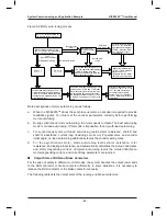
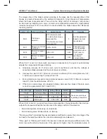
1. Check the field mechanical and electric wiring.
Before power-on, check the peripheral wiring to ensure component and personal safety.
The items to be checked include:
1) Whether the component models are matched
2) Whether the safety circuit is conducted and reliable
3) Whether the door lock circuit is conducted and reliable
4) Whether the shaft is unobstructed, and the car has no passenger and meets the
conditions for safe running
5) Whether the cabinet and traction motor are well grounded
6) Whether the peripheral circuit is correctly wired according to the drawings of the vendor
7) Whether all switches act reliably
8) Whether there is short-circuit to ground by checking the inter-phase resistance of the
main circuit
9) Whether the elevator is set to the inspection state
10) Whether the mechanical installation is complete (otherwise, it will result in equipment
damage and personal injury)
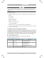
2. Check the encoder.
The pulse signal from the encoder is critical to accurate control of the system. Before
commissioning, check the following items carefully:
1) The encoder is installed reliably with correct wiring. For details on the encoder wiring,
see section 3.7.
2) The signal cable and strong-current circuit of the encoder are laid in different ducts to
prevent interference.
3) The encoder cable is preferably directly connected to the control cabinet. If the cable
is not long enough and an extension cable is required, the extension cable must be
a shielding cable and preferably welded to the original encoder cable by using the
soldering iron.
4) The shielding cable of the encoder cable is grounded on the end connected to the
controller (only one end is grounded to prevent interference).
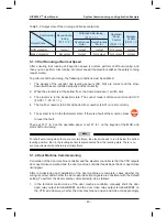
3. Check the power supply before power-on.
1) The inter-phase voltage of the user power supply is within (380 V
±
15%), and the
unbalance degree does not exceed 3%.
2) The power input voltage between terminals 24V and COM on the MCB is within (24
VDC
±
15%).
3) The total lead-in wire gauge and total switch capacity meet the requirements.
Summary of Contents for NICE3000 New
Page 1: ......
Page 13: ......
Page 14: ...1 Safety Information and Precautions ...
Page 21: ...Safety Information and Precautions NICE3000new User Manual 20 ...
Page 22: ...2 Product Information ...
Page 33: ...Product Information NICE3000new User Manual 32 ...
Page 34: ...3 Mechanical and Electrical Installation ...
Page 67: ...4 Use of the NICE3000new ...
Page 79: ...5 System Commissioning and Application Example ...
Page 105: ...6 Function Code Table ...
Page 136: ...Function Code Table NICE3000new User Manual 134 ...
Page 137: ...7 Description of Function Codes ...
Page 205: ...8 EMC ...
Page 214: ...EMC NICE3000new User Manual 212 ...
Page 215: ...9 Troubleshooting ...
Page 230: ......
Page 233: ......