


Mechanical and Electrical Installation NICE3000
new
User Manual
- 36 -
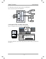
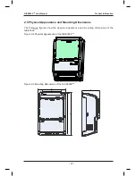
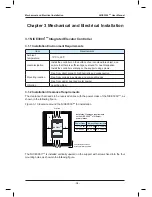
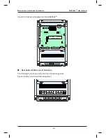
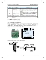
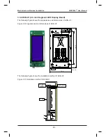
Figure 3-3 Terminal arrangement of the NICE3000
new
CN5
CN12
PRG
UP
SET
J9
J10
COP
HOP
CAN
2
232
CN1
CN9
J5
J1
CN3
CN2
CN7
CN4
J7
NICE3000
new
integrated
elevator controller
J12
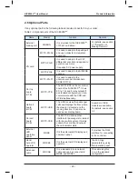
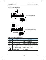
■
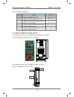
Description of Main Circuit Terminals
The following figure shows main circuit terminal arrangement.
Figure 3-4 Main circuit terminal arrangement
R
S
T
PB
U
V
W
POWER
MOTOR
Summary of Contents for NICE3000 New
Page 1: ......
Page 13: ......
Page 14: ...1 Safety Information and Precautions ...
Page 21: ...Safety Information and Precautions NICE3000new User Manual 20 ...
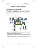
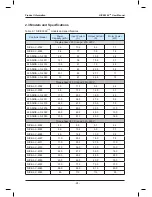
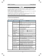
Page 22: ...2 Product Information ...
Page 33: ...Product Information NICE3000new User Manual 32 ...
Page 34: ...3 Mechanical and Electrical Installation ...
Page 67: ...4 Use of the NICE3000new ...
Page 79: ...5 System Commissioning and Application Example ...
Page 105: ...6 Function Code Table ...
Page 136: ...Function Code Table NICE3000new User Manual 134 ...
Page 137: ...7 Description of Function Codes ...
Page 205: ...8 EMC ...
Page 214: ...EMC NICE3000new User Manual 212 ...
Page 215: ...9 Troubleshooting ...
Page 230: ......
Page 233: ......