


NICE3000
new
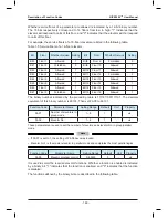
User Manual Description of Function Codes
- 145 -
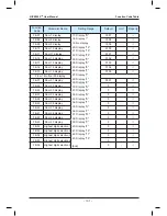
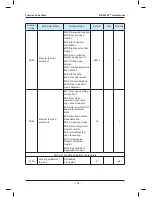
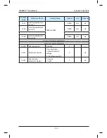
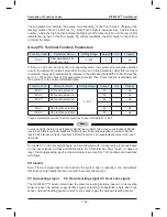
Function Code
Parameter Name
Setting Range
Default
Unit
Property
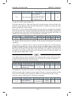
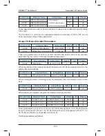
F3-08
Special deceleration rate
0.500–2.000
0.900
m/s
2
★
It is used to set the deceleration rate in elevator slow-down, inspection, and shaft auto-tuning.
This parameter is not used during normal running. It is used only when the elevator position
is abnormal or the slow-down signal is abnormal, preventing over travel top terminal or over
travel bottom terminal.
Function Code
Parameter Name
Setting Range
Default
Unit
Property
F3-09
Pre-deceleration distance
0–90.0
0.0
mm
★
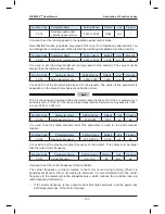
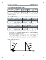
It is used to set the pre-deceleration distance of the elevator in distance control, as shown
in Figure 7-2. This function is to eliminate the effect of encoder signal loss or leveling signal
delay.
Function Code
Parameter Name
Setting Range
Default
Unit
Property
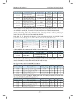
F3-10
Re-leveling speed
0.000–0.080
0.040
m/s
★
is used to set the elevator speed during re-leveling.
This parameter is valid only when the pre-open module (MCTC-SCB-A) is added to
implement the re-leveling function (set in FE-32).
Function Code
Parameter Name
Setting Range
Default
Unit
Property
F3-11
Inspection speed
0.100–0.630
0.250
m/s
★
It is used to set the elevator speed during inspection and shaft auto-tuning.
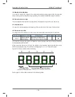
Function Code
Parameter Name
Setting Range Default Unit
Property
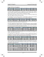
F3-12
Position of up slow-down 1
0.000–300.00
0.00
m
★
F3-13
Position of down slow-down 1
0.000–300.00
0.00
m
★
F3-14
Position of up slow-down 2
0.000–300.00
0.00
m
★
F3-15
Position of down slow-down 2
0.000–300.00
0.00
m
★
F3-16
Position of up slow-down 3
0.000–300.00
0.00
m
★
F3-17
Position of down slow-down 3
0.000–300.00
0.00
m
★
These parameters specify the positions of all slow-down switches relative to the bottom
leveling position, and the positions are automatically recorded during shaft auto-tuning. For
the installation positions of the slow-down switches, see the description of section 3.8.2.
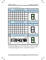
The NICE3000
new
integrated elevator controller supports a maximum of three pairs of slow-
down switches. From two sides of the shaft to the middle, slow-down 1, slow-down 2, and
slow-down 3 are installed in order; that is, slow-down 1 is installed near the terminal floor.
There may be only one pair of slow-sown switches for the low-speed elevator, and two or
three pairs of slow-down switches for the high-speed elevator.
The system automatically detects the speed when the elevator reaches a slow-down switch.
If the detected speed or position is abnormal, the system enables the elevator to slow down
at the special deceleration rate set in F3-08, preventing over travel top terminal or over
travel bottom terminal.
Summary of Contents for NICE3000 New
Page 1: ......
Page 13: ......
Page 14: ...1 Safety Information and Precautions ...
Page 21: ...Safety Information and Precautions NICE3000new User Manual 20 ...
Page 22: ...2 Product Information ...
Page 33: ...Product Information NICE3000new User Manual 32 ...
Page 34: ...3 Mechanical and Electrical Installation ...
Page 67: ...4 Use of the NICE3000new ...
Page 79: ...5 System Commissioning and Application Example ...
Page 105: ...6 Function Code Table ...
Page 136: ...Function Code Table NICE3000new User Manual 134 ...
Page 137: ...7 Description of Function Codes ...
Page 205: ...8 EMC ...
Page 214: ...EMC NICE3000new User Manual 212 ...
Page 215: ...9 Troubleshooting ...
Page 230: ......
Page 233: ......