


Mechanical and Electrical Installation NICE3000
new
User Manual
- 46 -
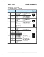
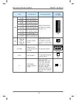
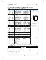
Terminal
Name
Function
Terminal Wiring
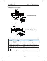
CN1
Modbus communication and power supply terminal
Pins 2 and 3 are for Modbus communication.
Pins 1 and 4 are for DC power supply.
1 2 3 4
MOD
-
MOD
+
24
V
COM
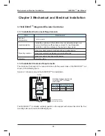
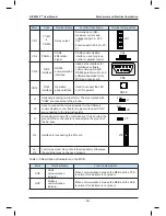
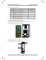
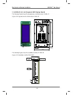
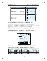
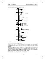
3.3.2 HCB-R1 (Ultrathin Dot-Matrix Display Board)
The following figure shows the appearance and dimensions of HCB-R1.
Figure 3-10 Appearance and dimensions of HCB-R1
4-
Φ
3.5
56.0
134
.0
144
.0
22.8
39
.0
CN1
J1
UP DOWNST XF
70
MCTC-HCB-R1
Unit: mm
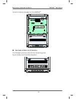
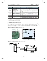
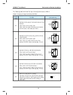
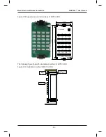
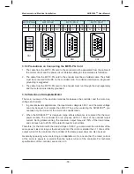
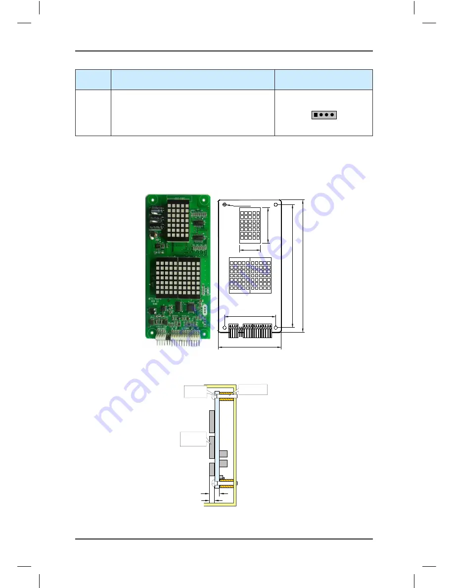
The following figure shows the installation method of HCB-R1.
Figure 3-11 Installation method of HCB-R1
6.7
Ultrathin dot-
matrix display
board
HCB-R1
Self-tapping
screw
4-
Φ
4.9x30
Plastic support
higher than 1 cm
10
Summary of Contents for NICE3000 New
Page 1: ......
Page 13: ......
Page 14: ...1 Safety Information and Precautions ...
Page 21: ...Safety Information and Precautions NICE3000new User Manual 20 ...
Page 22: ...2 Product Information ...
Page 33: ...Product Information NICE3000new User Manual 32 ...
Page 34: ...3 Mechanical and Electrical Installation ...
Page 67: ...4 Use of the NICE3000new ...
Page 79: ...5 System Commissioning and Application Example ...
Page 105: ...6 Function Code Table ...
Page 136: ...Function Code Table NICE3000new User Manual 134 ...
Page 137: ...7 Description of Function Codes ...
Page 205: ...8 EMC ...
Page 214: ...EMC NICE3000new User Manual 212 ...
Page 215: ...9 Troubleshooting ...
Page 230: ......
Page 233: ......