


NICE3000
new
User Manual Description of Function Codes
- 157 -
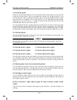
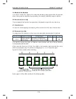
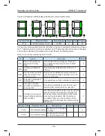
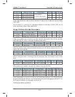
These parameters are used to monitor the state of all I/O terminals of the system.
The LEDs of F5-34/F5-35 are arranged as 5, 4, 3, 2, 1 from left to right.
Figure 7-6 Monitoring of all I/O terminals
1
2
3
4
5
A
B
C
D
E
F
G
DP
A
B
C
D
E
F
G
DP
A
B
C
D
E
F
G
DP
A
B
C
D
E
F
G
DP
A
B
C
D
E
F
G
DP
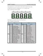
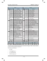
Each segment of the LEDs is defined in the following table.
Table 7-4 Definition of LED segments
F5-34
F5-35
No. Segment
Indication
No. Segment
Indication
1
A
-
1
A
Light curtain 1
B
Up leveling signal
B
Light curtain 2
C
Down leveling signal
C
Door 1 open limit
D
Door zone signal
D
Door 2 open limit
E
Safety circuit feedback 1
E
Door 1 close limit
F
Door lock circuit feedback 1
F
Door 2 close limit
G
RUN contactor feedback
G
Full-load signal
DP
Brake contactor feedback 1
DP
Overload signal
2
A
Inspection signal
2
A
Door open button
B
Inspection up signal
B
Door close button
C
Inspection down signal
C
Door open delay button
D
Fire emergency signal
D
Bypass signal
E
Up limit signal
E
Attendant signal
F
Down limit signal
F
Direction change signal
G
Overload signal
G
Independent running signal
DP
Full-load signal
DP
Firefighter operation signal
Summary of Contents for NICE3000 New
Page 1: ......
Page 13: ......
Page 14: ...1 Safety Information and Precautions ...
Page 21: ...Safety Information and Precautions NICE3000new User Manual 20 ...
Page 22: ...2 Product Information ...
Page 33: ...Product Information NICE3000new User Manual 32 ...
Page 34: ...3 Mechanical and Electrical Installation ...
Page 67: ...4 Use of the NICE3000new ...
Page 79: ...5 System Commissioning and Application Example ...
Page 105: ...6 Function Code Table ...
Page 136: ...Function Code Table NICE3000new User Manual 134 ...
Page 137: ...7 Description of Function Codes ...
Page 205: ...8 EMC ...
Page 214: ...EMC NICE3000new User Manual 212 ...
Page 215: ...9 Troubleshooting ...
Page 230: ......
Page 233: ......