VS
07.94
1-108
Siemens AG 1997 All Rights reserved
SIMODRIVE 611A Installation and Start–Up Guide/IAA/–04.97 Edition
Function
Component(s)
Effect
Travel to end stop
(variable via terminal 96)
R12 = open (as supplied)
voltage at terminal 96 according
to Fig. 3-4
Limiting acc. to Fig. 3-4,
n–contr. monitoring inactive
Setting–up operation
(central, via terminal 112 on the
NE module)
R12 according to
Fig. 3-3
terminal 112 = open
(when supplied, terminal 112 to
terminal 9)
Limiting according to Fig.KEIN MERKER,
Speed controller monitoring inactive
Current reduced after timer, n
controller at end stop, has expi-
red
R2 according to Fig. 3-5
R32 = open
Reduction acc. to Fig. 3-5
n–contr. monit. disabled
Current reduced after the I
2
t ti-
mer has expired
R2 = open (as supplied)
R32 = open
S1–duty = 1.1 I
rated
Response threshold I
2
t
R9 = 30 k
Ω
(as supplied)
R9 according to Fig. 3-6
S1–duty = 1.1 I
rated
Limiting acc. to Fig. 3-6
Electronic weight equalization
1)
R46 + R48 = open (as supplied)
R46 for neg. I set at socket T
R48 for pos. I set at socket T
no weight equalization
Suppl. I set acc. to Fig. 3-7
Suppl. I set acc. to Fig. 3-7
Tachometer adaptation
2)
R6, R7, R8 tolerance
0.1%
(
5
k
–1
V
tach.
V
tach.X
)
–7.5
k
1
4
(
V
tach.
V
tach.X
)
]
[
R
x
=
Clock frequency
R542
Refer to Fig.3-1
[%]
I
set
I
max
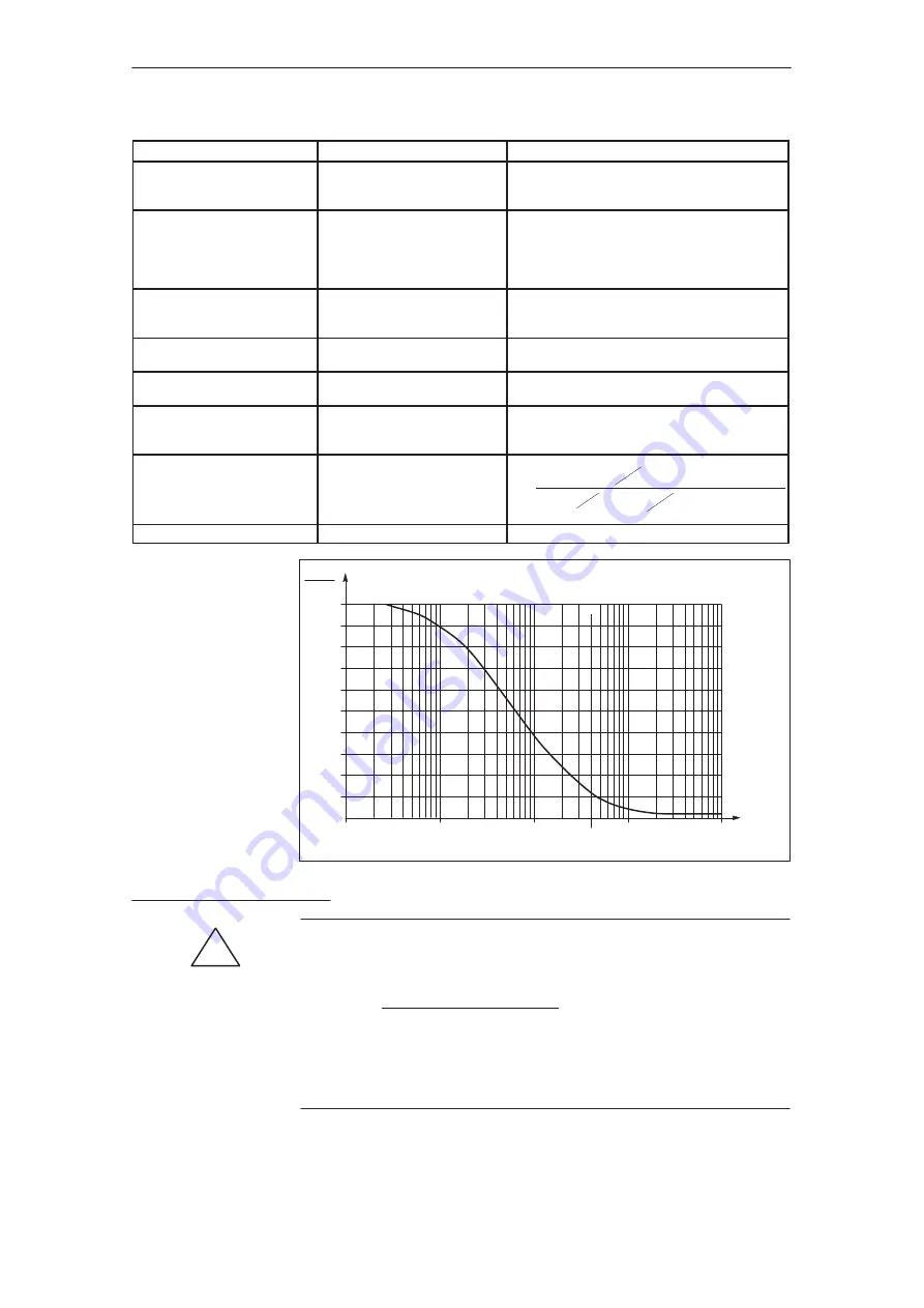
0.1 1.0 10.0 100.0 1000.0
R12 [k
]
100
90
80
70
60
50
40
30
20
10
0
Final
value
1%
Fig. 3-3 Current setpoint limiting as a function R12,
j
30 V
j
terminal 96
j
12 V
j
!
1)
Warning
For version 4620087701.00 of the control board, for weight compensation, the
internal current setpoint must be reduced via R42!
R42 [k
] =
20
I weight equalization/I
max
1 – I weight compensation/I
max
For control boards, from version 4620087701.01 onwards, zero offset cannot be
measured after R46 and R48 have been mounted and an axis enabled. If R46
and R48 have been correctly mounted according to Fig. 3-7, the offset must be
able to be measured when the axis is inhibited.
2) Refer to p. 1-105, "c) Tachometer adaption".
Feed modules (VS)
04.97
3.2 Setting elements with user–friendly interface
Summary of Contents for SIMODRIVE 611A
Page 2: ......
Page 6: ......
Page 7: ...SECTION 0 PRELIMINARY INFORMATION 0 7 ...
Page 8: ......
Page 17: ...Section 1 611A Analog Feed Drives 1 17 ...
Page 18: ...1 18 ...
Page 24: ...1 24 ...
Page 39: ...1 39 ...
Page 70: ...1 70 ...
Page 119: ...1 119 ...
Page 120: ......
Page 123: ......
Page 131: ......
Page 158: ...1 158 ...
Page 159: ...1 159 MOUNTING DIMENSIONS ...
Page 160: ...1 160 ...
Page 186: ......
Page 187: ...GENERAL INFORMATION REGARDING AC SERVO MOTORS AL S ...
Page 188: ......
Page 225: ...1FT5 AC SERVO MOTOR DESCRIPTIONS 1FT5 ...
Page 226: ......
Page 321: ...FEEDBACK DEVICES FOR 1FT5 GE ...
Page 322: ......


