84
Display Menu, Matrix
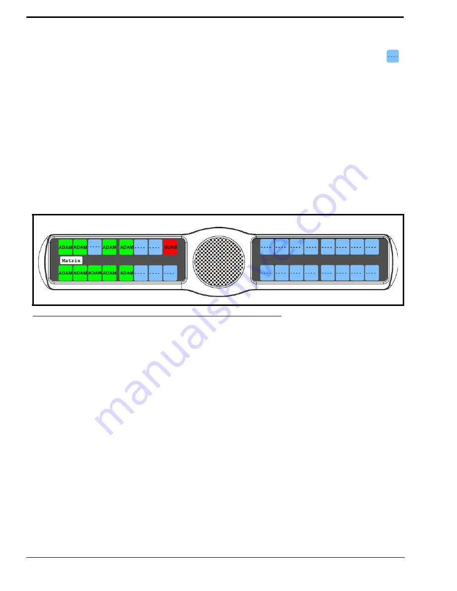
Matrix
displays the intercom system name for all talk level 1 key assignments. The local intercom is represented by a green
key, while a remote intercom is represented by a red key. If a key assignment is not present on a key, an unassigned key
displays.
In non-trunked intercom systems, the intercom system name is always LOCL (local). In trunked systems, intercom system
names are created in TrunkEdit (
Intercoms|Names
).
To
display the matrix intercom system name
, do the following:
1.
On the KP 32 CLD keypad, press
MENU
.
The Top Level menu appears
.
2.
Verify
Display
is selected.
3.
Press the
SEL
button.
The Display submenu appears
.
4.
Using the 3(
↑
)
or 6(
↓
)
,
select
Matrix
.
5.
Press the
SEL
button.
The Matrix display appears showing the matrix intercom system (see Figure 79).
Display Menu, Panel ID
Panel ID
displays the port number to which the keypanel is connected (used only with an AIO-8 card). The calculation is
based on the data group to which the keypanel is connected. If the address switch is incorrectly set, the wrong panel ID
displays. There is no need for this address if an AIO-16 card is used. Address setting is automatically generated when an
AIO-16 card is used.
NOTE:
When the keypanel is not scroll enabled, the Panel ID displays only the port number in the panel display window.
When the keypanel is scroll enabled, the port number and port alpha are displayed.
To
display the panel ID
, do the following:
1.
On the KP 32 CLD keypad, press
MENU
.
The Top Level menu appears
.
2.
Verify
Display
is selected.
3.
Press the
SEL
button.
The Display submenu appears
.
4.
Using the 3(
↑
)
or 6(
↓
)
,
select
Panel ID
.
5.
Press the
SEL
button.
The Panel ID display appears showing the port number and alpha (if applicable) for the keypanel (see Figure 80).
FIGURE 79.
Display Menu - Matrix
Summary of Contents for CLD Color Keypanel Family DKP 16 CLD
Page 1: ...CLD Color Keypanel Family User Manual 93507858000 Rev B 8 2008 KP 32 CLD DKP 16 CLD EKP 32 CLD...
Page 8: ......
Page 11: ...5 KP 32 CLD Block Diagram FIGURE 1 KP 32 CLD Block Diagram...
Page 26: ...20...
Page 47: ...41 NOTE The KP 32 CLD resets itself once the firmware download is complete...
Page 52: ...46...
Page 55: ...49 FIGURE 23 Main Audio Options Menu...
Page 142: ...136...
Page 143: ...137 CHAPTER 8 Keypanel Menu Quick Reference...
Page 146: ...140 FIGURE 144 Service Menu for the KP 32 CLD with GPI 32 CLD Option card installed...
Page 150: ...144...
Page 154: ...148...
Page 156: ...150...
Page 160: ......


