background image

8

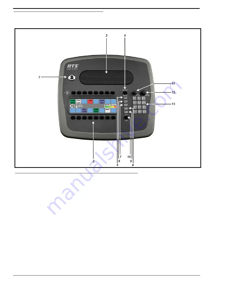
Reference View DKP 16 CLD 
(90007866000)

Front Panel Descriptions

1.

1 1/4” Stereo Jack - Panel Mic

2.

Keypanel Keys - Press down to talk, press up to listen. 
For more information, see “Basic Intercom Key 
Operation” on page 28

3.

Panel Speaker - For more information, see “Mute the 
Microphone/Speaker” on page 34

4.

Mic Mute / Mic Sel - When the key is pressed up, all 
active mics are muted. When the key is pressed down the 
focus switches between the selected headset or panel mic. 

NOTE:

Panel Mic indicates front or rear 

panel mic. Or, it indicates the front 
or rear headset speaker. The 
configuration of this feature is 
dependent upon the Audio Out 
configuration (see “Audio Options 
Menu, Speaker” on page 74).

5.

Menu button - For detailed explanation, see “KP 32 CLD 
Menu System” on page 47.

6.

FWD button - Allows you to go forward in the menu 
structure.

7.

BACK button - Allows you to go backward in the menu 
structure.

8.

UPG 1 button - User can assign any function from the 
menu structure to this key.

9.

UPG 2 button - User can assign any function from the 
menu structure to this key.

10.

CLR/CWW Key - Clears the panel menu or answers the 
call waiting window.

11.

Aux Volume - The Aux volume adjusts the volume of the 
Aux 1 through Aux 6 connections, the Matrix 
connections, and input channels from the option card 
(future). The range for this feature is

 Mute, -48dB to 

10dB

.

12.

Main Volume - The main volume adjusts the volume for 
the front speaker, rear speaker, front headset and rear 
headset.

13.

Keypad - The keypanel keypad is used to navigate 
through the KP 32 CLD menu structure, configure 
keypanel features, as well as utilize the TIF dial-out 
features.

FIGURE 4.

DKP 16 CLD - Top View

Summary of Contents for CLD Color Keypanel Family DKP 16 CLD

Page 1: ...CLD Color Keypanel Family User Manual 93507858000 Rev B 8 2008 KP 32 CLD DKP 16 CLD EKP 32 CLD...

Page 2: ...ory Service 800 553 5992 Please include a note in the box which supplies the company name address phone number a person to contact regarding the repair the type and quantity of equipment a description...

Page 3: ...tments 30 Operation of Intercom Keys with Auto Functions 32 Operation of Intercom Keys with Options 32 GROUP OPTION KEYS 32 SOLO KEY 32 Operation of Intercom Talk Keys with the Speaker DIM Setting 32...

Page 4: ...02 KEY OPTIONS MENU LATCHING 103 KEY OPTIONS MENU SOLO 104 KEY OPTIONS MENU TALLIES 105 Menu System RVON Offers 106 Menu System Save Config 107 Menu System Service 108 SERVICE MENU ALPHA SIZE 109 SERV...

Page 5: ...19 Aux Volume Adjustment Aux 1 31 FIGURE 20 User Select Quick Scroll 33 FIGURE 21 All Muted Display Icons 34 FIGURE 22 Top Level Menu Structure 47 FIGURE 23 Main Audio Options Menu 49 FIGURE 24 Audio...

Page 6: ...FIGURE 70 Main Display Menu 78 FIGURE 71 Assign Type Menu 79 FIGURE 72 Chans On 80 FIGURE 73 Display Menu Chime 81 FIGURE 74 Display Menu Exclusive 81 FIGURE 75 Display Menu Key Groups 82 FIGURE 76 D...

Page 7: ...125 FIGURE 133 Snoop Tallies Disable 125 FIGURE 134 Service Menu Test Panel 126 FIGURE 135 TIF Operation Manual Dial Feature 128 FIGURE 136 TIF Operation Manual Dial Dial Number 128 FIGURE 137 TIF Ope...

Page 8: ......

Page 9: ...in different colors Modern Modular Design Flat front panel is ergonomically designed to fit easily into any control room or truck application The back panel is optimized for future expansion Multi Dir...

Page 10: ...rts RTS RJ 11 cabling or Standard Cat5 cabling See RJ 45 Frame RTS RJ11 Cable and DB 9 male Frame on page 12 for pinouts Expansion RJ 45 see RJ 45 EXP expansion on page 13 for pinouts GPIO MIC OUT Mal...

Page 11: ...5 KP 32 CLD Block Diagram FIGURE 1 KP 32 CLD Block Diagram...

Page 12: ...Menu Speaker on page 74 7 CLR CWW Key Clears the panel menu or answers the call waiting window 8 Menu button For detailed explanation see KP 32 CLD Menu System on page 47 9 FWD button Allows you to go...

Page 13: ...Function on page 42 Optional GPI 32 CLD Module 7 DB 15 Connector Aux 3 through Aux 6 8 DB 9 male Connector Relay 1 2 3 9 DB 9 male Connector Opto 1 4 IN 10 DB 9 male Connector OC 1 and 2 OUT 11 DB 9 m...

Page 14: ...anation see KP 32 CLD Menu System on page 47 6 FWD button Allows you to go forward in the menu structure 7 BACK button Allows you to go backward in the menu structure 8 UPG 1 button User can assign an...

Page 15: ...pin XLR female for Headset 6 7 pin XLR female for Headset and Footswitch connection 3 Left side 4 5 pin XLR female for Headset 6 7 pin XLR female for Headset and Footswitch connection FIGURE 5 DKP 16...

Page 16: ...female Connector Frame 4 RJ 45 Connector Frame 5 XLR 3 female Connector Aux 1 6 XLR 3 female Connector Aux 2 7 DB 9 Connector Aux 3 Footswitch and Speaker 8 DB 9 male Connector Opto 1 3 IN 9 XLR 3 mal...

Page 17: ...ux 4 Aux 5 Aux 6 Pin Assignment 1 AUX 3 Input 2 AUX 3 Input 3 AGND 4 AUX 4 Input 5 AUX 4 Input 6 AGND 7 DGND 8 5VD 9 AGND 10 AUX 5 Input 11 AUX 5 Input 12 AUX 6 Input 13 AUX 6 Input 14 DGND 15 5VD DB...

Page 18: ...AGND XLR 3 female AUX 1 2 Pin Assignment 1 GND 2 Input 3 Input XLR 3 female Mic IN Pin Assignment 1 AGND 2 Audio and DC Bias 3 AGND XLR 3 male Mic OUT Pin Assignment 1 AGND 2 Audio Output 3 Audio Out...

Page 19: ...atrix 4 Audio OUT to Matrix 5 Audio OUT to Matrix 6 Audio IN from Matrix 7 RS485 pair 7 8 8 RS485 pair 7 8 RJ 45 EXP expansion Pin Assignment 1 GND 2 GND 3 GND 4 GND 5 RS485 6 RS485 7 GND 8 Reserved R...

Page 20: ...witch bank do the following 1 Remove the four 4 screws on the top of the unit shown in Figure 7 2 In no certain order remove the following screws shown in Figure 8 FIGURE 7 KP 32 CLD Top Screw Removal...

Page 21: ...he back panel Note the back panel is still attached by the DB 9 Frame ribbon cable 4 Using a pointed object set the switches to the type of operation you desire For operation modes see Figure 10 Figur...

Page 22: ...ON Switch 2 OFF Switch 3 ON Switch 4 OFF FIGURE 11 Use this switch setting scheme for a Standard CAT 5 Cable using pin 1 and pin 2 for RS485 functionality 568B Switch 1 OFF Switch 2 ON Switch 3 OFF S...

Page 23: ...o the power connector KP 32 CLD 2 If required set the keypanel address 3 Connect an RJ11 cable with RTS cabling E or RJ45 cable with RTS cabling F to the frame connector see Figure 13 OR Connect a DB9...

Page 24: ...varies for each intercom system Use the method for your intercom system as described on the following pages To see specific addressing information for ADAM with AIO 8 cards see the ADAM installation...

Page 25: ...arate microphone Headphones may be connected for use with a separate microphone Panel Microphone Connector A panel microphone may be connected to the front or rear with optional GPI 32 CLD option card...

Page 26: ...20...

Page 27: ...2 Default Key Colors to help you determine the available key assignment colors TABLE 2 Default Key Colors Default Color Description Amber Waiting for Footswitch Bright Green Talk ON Brown IFB Special...

Page 28: ...Active The footswitch is active Footswitch Enabled The footswitch is enabled but not active NOTE When a keypanel key is pressed while the Footswitch is enabled the key display turns amber to signify...

Page 29: ...any active mics when the mic mute key is pressed If tone is enabled which disables mics the mute icon appears on any active mic but does not flash Rear Speaker The rear speaker is active To activate t...

Page 30: ...bled to use snoop tallies To enable snoop tallies see Service Menu Snoop Tally on page 124 Hot Mic The hot mic is active To activate Hot Mic see Audio Options Menu Matrix Out on page 69 Tone 1kHz Enab...

Page 31: ...SEL button Default Keypad For information on Default keypad sequences see Default Keypad Sequence on page 134 For information on the Classic Keypad see Classic Keypad Sequence on page 132 KEYPAD BUTTO...

Page 32: ...d then tap the keypanel key where THRE is to be assigned CLR DROP button The CLR DROP button is used to clear the CWW window or exit out of the menu structure If the CLR DROP button is pressed when in...

Page 33: ...on when in TIF mode is used to dial out from the keypanel TABLE 4 INFO Button Feature and Option Descriptions Graphical Representation FEATURE DESCRIPTION Id Displays the port ID where the keypanel is...

Page 34: ...his feature allows the user to adjust the volume for individual keys on the keypanel Figure 14 displays the different key positions and their meanings Ver Displays the firmware version currently loade...

Page 35: ...ey to the left to decrease the listen gain for the selected key assignment A volume status bar and the volume level in dB appear on the specified key in the display window Listen Volume Adjustments By...

Page 36: ...lowing On the KP 32 CLD push the MAIN VOLUME encoder once The listen destination main volume focus switches to next listen destination shown if applicable Aux Volume Adjustments By default the Aux Vol...

Page 37: ...display window see Figure 16 NOTE You can save the volume adjustments to be power up defaults using Service Menu Save Cfg NOTE The listen source appears in the Aux Volume menu if they are enabled or...

Page 38: ...the crosspoint levels to diminish for any other intercom ports currently listening to the same destination and are in the same DIM tables Operation of Intercom Keys with Options Group Option Keys Acti...

Page 39: ...he list of point to point connections available The selected port is highlighted in white NOTE You can also use the 5 or 3 to page scroll through the list of ports available Page scroll is useful when...

Page 40: ...the call waiting window option found in AZedit Options Intercom Configuration Options Setting this option in AZedit overrides the DIP Switch 2 setting on the Master Controller Mute the Microphone Spe...

Page 41: ...he audio is sent NOTE You must configure the source on the keypanel for the type of operation you require For more information see Audio Options Menu Headset on page 62 Audio Options Menu Panel Mic on...

Page 42: ...set mic are configured as Always ON the external panel mic is not available Speaker Front and Rear Front Rear Rear Front Front Rear Rear Front Front and Rear No icons display on the keypanel Headset F...

Page 43: ...ppears 2 Using the 3 or 6 navigate to the menu item you want to assign to either UPG 1 or UPG 2 3 Press and hold the UPG key for two 2 seconds Menu position saved appears in the display window To assi...

Page 44: ...Press SEL The screen saver activates on the keypanel 7 Press and hold the UPG key you want to assign this option to for two 2 seconds Menu position saved appears in the display window and the screen s...

Page 45: ...ble for all CLD family keypanels however the instructions below display the KP 32 CLD Download Firmware to the Color Keypanel Family From AZedit 1 Open AZedit 2 From the Status menu select Port The Po...

Page 46: ...Using the browse button browse to the file to be downloaded 7 Click Open The Download Device Firmware window appears 8 Click Begin Download The download begins 9 Click OK The KP 32 CLD firmware downl...

Page 47: ...41 NOTE The KP 32 CLD resets itself once the firmware download is complete...

Page 48: ...le for all CLD family keypanels however the instructions below display the KP 32 CLD The BLR Boot Loader Reset button is used to upload new firmware to a keypanel with a corrupt bad image installed To...

Page 49: ...he display window 4 In AZedit from the Status menu select Software Versions The Software Versions popup menu appears 5 From the Software Versions popup menu select Keypanels The Keypanel Version Infor...

Page 50: ...ce Firmware window appears 11 Click Begin Download The Download begins and a popup message appears 12 Click OK The KP 32 CLD firmware download finishes This can take up to 20 minutes to complete Use t...

Page 51: ...45 NOTE Once the Boot Loader is finished downloading it reboots itself The KP 32 CLD displays one of two messages shown below If the download is brand new you will see message 1 Message1...

Page 52: ...46...

Page 53: ...level of the menu structure for the KP 32 CLD This menu has the following selections Audio Options Display Key Assign Key Options RVON Offers Save Config Service To access the main menu structure for...

Page 54: ...tem Audio Options The information available for audio options is as follows Dim DSP Funcs Headset Headset Mic Key Volumes Mic Gain Min Volume Max Volume Matrix Out Output Lvl Panel Mic Sidetone Speake...

Page 55: ...49 FIGURE 23 Main Audio Options Menu...

Page 56: ...ons 3 Press the SEL button The Audio Options menu appears 4 Using the 3 or 6 select Dim 5 Press the SEL button Headset and Speaker appear in the display window 6 Using the 3 or 6 select Headset to set...

Page 57: ...ons menu appears 4 Using the 3 or 6 select DSP Funcs 5 Press the SEL button Equalization Filters Gating Metering and Mixing appears in the display window Equalization Equalization allows the user to s...

Page 58: ...52 The presets are as follows FIGURE 26 Frequency Response Preset 1 20Hz to 300Hz FIGURE 27 Frequency Response Preset 2 300Hz to 900Hz...

Page 59: ...53 FIGURE 28 Frequency Response Preset 3 900Hz to 2100Hz FIGURE 29 Frequency Response Preset 4 2100Hz to 4500Hz...

Page 60: ...io Options submenu appears 4 Using the 3 or 6 select DSP Funcs 5 Press the SEL button The DSP Funcs menu appears in the display window 6 Using the 3 or 6 select Equalization 7 Press the SEL button Fro...

Page 61: ...his feature is only available when GPI 32 CLD option card is installed Headset Mic Panel Mic Rear Headset Mic This feature is only available when GPI 32 CLD option card is installed Rear Panel Mic Thi...

Page 62: ...ou to minimize or eliminate background noise problems by shutting OFF an audio source when the sound level drops below a certain threshold You can set gating thresholds on the following Aux 1 6 This f...

Page 63: ...or 6 select Gating 7 Press the SEL button Aux In 1 Aux In 2 Aux In 3 Aux In 4 Aux In 5 Aux In 6 Front Hdst Front Mic Matrix In Rear Hdst and Rear Mic appear in the display window 8 Using the 3 or 6 s...

Page 64: ...keypanel when enabled The dB display range is from 28dB below nominal to 8dB above nominal The ranges are as follows By default None is configured for metering NOTE Only one channel can be metered at...

Page 65: ...cs 5 Press the SEL button The DSP Funcs menu appears in the display window 6 Using the 3 or 6 select Metering 7 Press the SEL button Aux In 1 Aux In 2 Aux In 3 Aux In 4 Aux In 5 Aux In 6 Matrix In Non...

Page 66: ...llowing 1 On the KP 32 CLD keypad press MENU The Top Level menu appears 2 Using the 3 or 6 select Audio Options 3 Press the SEL button The Audio Options submenu appears 4 Using the 3 or 6 select DSP F...

Page 67: ...or 6 select the Output you want to mix 9 Press the SEL button Aux In 1 Aux In 2 Aux In 3 Aux In 4 Aux In 5 Aux In 6 and Matrix In appear in the display window 10 Using the 3 or 6 select the Input you...

Page 68: ...of the Hdst Panel Mic See Reference View KP 32 CLD 90007858000 on page 6 NOTE When using the DKP 16 CLD Left and Right appear as options instead of Front and Rear To configure the Headset do the foll...

Page 69: ...peaker headphone is active NOTE When using the DKP 16 CLD Left and Right appear as options instead of Front and Rear To configure the Headset Mic do the following 1 On the KP 32 CLD keypad press MENU...

Page 70: ...om this menu item you can reset all the modified key gains back to their default settings NOTE Key Volumes are either enabled for the entire keypanel or disabled for the entire keypanel This setting c...

Page 71: ...2 Using the 3 or 6 select Audio Options 3 Press the SEL button The Audio Options submenu appears 4 Using the 3 or 6 select Key Volumes 5 Press the SEL button Adjust and Reset appear in the display win...

Page 72: ...can be configured from 20dB to 10dB To set the mic gain level do the following 1 On the KP 32 CLD keypad press MENU The Top Level menu appears 2 Using the 3 or 6 select Audio Options 3 Press the SEL...

Page 73: ...ress the CLR button The mic gain level is set To enable disable the mic gain level adjustment from the front mic select switch for the KP 32 CLD do the following 1 On the KP 32 CLD keypad press MENU T...

Page 74: ...olume level in dB for both the keypanel speaker and or the headset speaker This is the minimum volume level available on the volume control located on the front of the KP 32 CLD By default Min Volume...

Page 75: ...allows the user to select between Normal or Hot Mic In the Normal setting audio from the selected active mic based on the mic select feature see Audio Options Menu Panel Mic on page 72 goes out to the...

Page 76: ...user The default setting is 10dB but can be adjusted up or down to address individual user needs The Maximum Volume range is 48dB to 10dB and Mute To set the max volume for the headset do the followin...

Page 77: ...adjust the nominal audio output level to the matrix from 0dB to 8dB By default the Output Level is set to 8dB To set the output level do the following 1 On the KP 32 CLD keypad press MENU The Top Lev...

Page 78: ...r 6 select Audio Options 3 Press the SEL button The Audio Options menu appears 4 Using the 3 or 6 select Panel Mic 5 Press the SEL button Front and Rear appear NOTE All four 4 mics cannot be enabled a...

Page 79: ...is heard only when the talk is activated To set the sidetone level do the following 1 On the KP 32 CLD keypad press MENU The Top Level menu appears 2 Using the 3 or 6 select Audio Options 3 Press the...

Page 80: ...32 CLD option card is installed Front and Rear options are displayed You can configure the speaker with one of the following Always ON no matter what is selected Always ON overrides the manual select...

Page 81: ...r is used to check the audio path from the keypanel to the matrix There are two tones available 500Hz Tone default 1kHz Tone The selected tone can be activated from either the menu or from the keypad...

Page 82: ...tone do the following 1 On the KP 32 CLD keypad press MENU The Top Level menu appears 2 Using the 3 or 6 select Audio Options 3 Press the SEL button The Audio Options menu appears 4 Using the 3 or 6...

Page 83: ...mp output connector When Disabled is selected keypanel audio is isolated from the preamp output connector NOTE The GPI 32 CLD option card must be installed for the Preamp Out menu item to appear The s...

Page 84: ...on The information available for display is as follows Assign Type Chans ON Chime Exclusive Key Groups Key List Level 2 Key Assignments Listen Assignments Matrix Panel ID Solo Key Keypanel Firmware Ve...

Page 85: ...frame or a relay output at a UIO 256 GPIO 16 or FR9528 frame Camera ISO Camera ISO Talk Key UPL RSRC UPL Resource Key IFB SL IFB Special List Key AC All Call Key To display the types of key assignmen...

Page 86: ...ON information do the following 1 On the KP 32 CLD keypad press MENU The Top Level menu appears 2 Verify Display is selected 3 Press the SEL button The Display submenu appears 4 Using the 3 or 6 selec...

Page 87: ...ears 2 Verify Display is selected 3 Press the SEL button The Display submenu appears 4 Using the 3 or 6 select Exclusive 5 Press the SEL button The Exclusive display appears showing exclusive keys in...

Page 88: ...Key List Key List displays and allows users to see all the other assignments on other keypanel pages not currently showing in the keypanel display To display the Key List information do the following...

Page 89: ...appears 4 Using the 3 or 6 select Level 2 5 Press the SEL button The Level 2 display appears showing the level 2 talk keys see Figure 77 Display Menu Listen Listen displays the listen assignments for...

Page 90: ...play Menu Panel ID Panel ID displays the port number to which the keypanel is connected used only with an AIO 8 card The calculation is based on the data group to which the keypanel is connected If th...

Page 91: ...t Solo 5 Press the SEL button The Solo display appears showing solo keys in red see Figure 81 NOTE You may only assign one solo key at a time Display Menu Version Version displays the firmware version...

Page 92: ...e SEL button The Display submenu appears 4 Using the 3 or 6 select Version 5 Press the SEL button The Version display appears showing firmware version for the keypanel see Figure 82 FIGURE 82 Display...

Page 93: ...ist Sys Relay Camera ISO UPL IFSL Auto Func To access the key assign menu options do the following 1 On the KP 32 CLD keypad press MENU The Top Level menu appears 2 Using the 3 or 6 select Key Assign...

Page 94: ...KP 32 CLD do the following 1 On the KP 32 CLD keypad press MENU The Top Level menu appears 2 Using the 3 or 6 select Key Assign 3 Press the SEL button The Key Assign submenu appears 4 Using the 3 or...

Page 95: ...to the Pt to Pt assignment if applicable 11 Press the SEL button Tap Key appears 12 Press down on the keypanel key position where you want the Pt to Pt assignment to appear The key color changes to t...

Page 96: ...ars 2 Using the 3 or 6 select Key Assign 3 Press the SEL button The Key Assign submenu appears 4 Using the 3 or 6 select Pt to Pt 5 Press the SEL button A scroll list of available ports appears 6 Usin...

Page 97: ...of available party lines appears 6 Using the 3 or 6 select the party line you want to assign to the keypanel key 7 Press the SEL button A list of auto functions appear See Figure 88 Auto Functions on...

Page 98: ...ist Spcl List assigns a key that talk and or listens to a special list The key is not available until members have been assigned to the special list in AZedit NOTE Special List members can be non keyp...

Page 99: ...types of control devices that can exist in the intercom system including The 8 GPI outputs from an ADAM Frame J11 on the XCP ADAM MC Breakout Panel The 8 GPI outputs from an ADAM CS Frame J903on the A...

Page 100: ...an ISO isolate assignment type to the key By default all ISOs are restricted To see ISOs you must select the appropriate scroll enable check box in AZedit To assign a Camera ISO to the keypanel key do...

Page 101: ...ton A scroll list of available UPLs appears 6 Using the 3 or 6 select the UPL you want to assign to the keypanel key 7 Press the SEL button A list of auto functions appear see Figure 88 Auto Functions...

Page 102: ...ton Tap Key appears 10 Press down on the keypanel key position where you want the IFSL assignment to appear The key color changes to brown and the alpha appears on the key Key Assign Menu Auto Func Au...

Page 103: ...button The Key Assign submenu appears 4 Using the 3 or 6 select Auto Funcs 5 Press the SEL button A scroll list of available Auto Funcs appears 6 Using the 3 or 6 select the auto function you want to...

Page 104: ...up to 100 stored auto dial numbers To store an auto dial number do the following 1 On the KP 32 CLD keypad press MENU The Top Level menu appears 2 Using the 3 or 6 select Key Options 3 Press the SEL b...

Page 105: ...g on the auto dial number you want to delete will determine the number seen here 8 Press FWD Save Number appears 9 Press the SEL button 01 empty appears in the display window The auto dial number is e...

Page 106: ...y appears in the display window 8 Tap down on each red keypanel key from which you want to remove the chime tone The selected keys return to the unassigned state light blue color 9 Press CLR to exit t...

Page 107: ...the following 1 On the KP 32 CLD keypad press MENU The Top Level menu appears 2 Using the 3 or 6 select Key Options 3 Press the SEL button The Key Options submenu appears 4 Using the 3 or 6 select Ex...

Page 108: ...to four 4 key groups To create a key group do the following NOTE Use the following instructions to create any of the four key groups 1 On the KP 32 CLD keypad press MENU The Top Level menu appears 2...

Page 109: ...o the unassigned state light blue color and Tap Slave Key s appears in the display window 9 Tap down on the keypanel keys you want to be activated when the master key is selected The selected keys tur...

Page 110: ...e 1 solo key To create a solo key do the following 1 On the KP 32 CLD keypad press MENU The Top Level menu appears 2 Using the 3 or 6 select Key Options 3 Press the SEL button The Key Options submenu...

Page 111: ...Options Menu Tallies Tallies are used to indicate incoming calls with blinking alpha assignments You can configure tally time as 15 seconds or an indefinite period of time If indefinite is chosen the...

Page 112: ...keypanel is connected to an RVON device otherwise the menu item is not available To access the RVON Offers menu do the following 1 On the KP 32 CLD keypad press MENU The Top Level menu appears 2 Usin...

Page 113: ...olatile memory This ensures your custom settings are saved when the keypanel is powered down To erase all custom settings you can run Reset Config see Service Menu Reset Cfg on page 120 To run a save...

Page 114: ...information available for key assign is as follows Alpha Size Aux Inputs Baud Rate Display Dim Footswitch Key View Keypad Local GPIO Reset Cfg RVON Setup Scrn Saver Set Address Snoop Tally Test Panel...

Page 115: ...Sizes available are 4 6 and 8 characters in length The default alpha size is 8 characters To set the alpha size for the display window do the following 1 On the KP 32 CLD keypad press MENU The Top Le...

Page 116: ...110 8 Using the 3 or 6 select Save and Restart 9 Press the SEL button Restarting appears in the panel display and then the keypanel cycles power FIGURE 112 Alpha Menu Restarting...

Page 117: ...x In 2 Aux In 3 Aux In 4 Aux In 5 Aux In 6 and Matrix In appear in the display window 6 Using the 3 or 6 select one of the inputs 7 Press the SEL button Disabled and Enabled appear in the display wind...

Page 118: ...right display window or both display windows Main Panel allows you to set the brightness for only the main keypanel You can set the brightness for the left display window the right display window or b...

Page 119: ...keypanel or the expansion panel Right adjusts the right display window on the keypanel or the expansion panel 9 Using the scroll arrows adjust the brightness 35 to 100 you want the keypanel to displa...

Page 120: ...button A blue arrow appears next to Disabled Service Menu Key View Key View allows the user to set the key view for the keypanel You can set the keypanel to display only Talk keys Talk Listen Keys or...

Page 121: ...d Quick Reference on page 131 To set the keypad sequence for the keypanel do the following 1 On the KP 32 CLD keypad press MENU The Top Level menu appears 2 Using the 3 or 6 select Service 3 Press the...

Page 122: ...for five 5 seconds of inactivity before shutting OFF However when the keypanel menu is active the backlight stays lit for one 1 minute before exiting the menu system and shutting OFF Using Activate a...

Page 123: ...master keys and a solo key Outputs can be activated by intercom keys NOTE This feature is only enabled if the GPI 32 CLD option card is installed NOTE The DKP 16 CLD has only three 3 Opto Connectors a...

Page 124: ...press MENU The Top Level menu appears 2 Using the 3 or 6 select Service 3 Press the SEL button The Service submenu appears in the display window 4 Using the 3 or 6 select Local GPIO 5 Press the SEL bu...

Page 125: ...5 Press the SEL button GPIO Inputs and GPIO Outputs appear in the display window 6 Using the 3 or 6 select GPIO Outputs 7 Press the SEL button OC Out 1 OC Out 2 Relay 1 Relay 2 and Relay 3 appear in t...

Page 126: ...el menu appears 2 Using the 3 or 6 select Service 3 Press the SEL button The Service submenu appears in the display window 4 Using the 3 or 6 select Reset Cfg 5 Press the SEL button Cancel and Do Rese...

Page 127: ...ur Mode Text NOTE Any action done to the keypanel directly or indirectly takes the keypanel out of screen saver mode To manually activate the screen saver do the following 1 On the KP 32 CLD keypad pr...

Page 128: ...e appear on the display window 6 Using the 3 or 6 select Delay 7 Press the SEL button Delay Time 1Hour appears 8 Using the 3 or 6 select the amount of time you want to expire before the screen saver a...

Page 129: ...trix The Poll ID number is directly related to the connection port on the breakout panel Example If the KP 32 CLD is connected to the breakout panel on J2 the poll ID for the keypanel is 2 Available o...

Page 130: ...1 has any talk keys turned on or if the hot mic is not enabled Snoop tallies are supported on KP 32 family keypanels NOTE Hot Mic must be activated on the keypanel for snoop tally to work To enable H...

Page 131: ...appears 2 Using the 3 or 6 select Service 3 Press the SEL button The Service submenu appears in the display window 4 Using the 3 or 6 select Snoop Tally 5 Press the SEL button Chime and No Chime defa...

Page 132: ...Key Descriptions All alpha numeric displays show a symbol on a red button when in Test Panel mode Pressing DOWN on any key causes OK to display on a green button with a red outline NOTE Pressing the C...

Page 133: ...tion Alternatively a no flash TIF key assignment indication can be provided This is accomplished by selecting the Don t generate tallies for TIF or trunk use in AZedit Options Intercom Configuration O...

Page 134: ...lephone from the KP 32 CLD do the following 1 On the KP 32 CLD press the TIF key down to turn it ON Auto Dial Hang Up Manual Dial and Redial appear in the display window 2 Using the 3 or 6 select Hang...

Page 135: ...ss 4 Dial Drop appear in the display window 2 Using the 3 or 6 select Drop Tap Key appears in the display window 3 Press and hold the desired UPG button 1 or 2 to which you want to program Hang Up The...

Page 136: ...Auto Dial Hang Up Manual Dial and Redial appear in the display window 3 Using the 3 or 6 select Auto Dial 4 Press SEL The Auto Dial numbers appear in the display window 5 Using the 3 or 6 select the...

Page 137: ...e two types of keypad sequences Classic and Default Classic sequence 2 is the previous standard for KP 32 and KP 96 keypanels Default sequence 1 is the new standard for the KP 32 CLD This sequence is...

Page 138: ...AR assignment 3 7 SEL PGM listen key Program a listen key with an AT assignment 3 5 SEL PGM talk key Program a talk key with an AC assignment 0 8 8 Show setup pages 0 8 9 Enter diagnostic menu 0 6 Di...

Page 139: ...GM key Program a key with a port assignment 2 PL num SEL PGM key Program a key with a PL assignment 0 1 SL num SEL PGM key Program a key with a SL assignment 0 2 IFB num SEL PGM key Program a key with...

Page 140: ...th an AR assignment 0 0 3 7 SEL listen key Program a listen key with an AT assignment 0 0 3 5 SEL talk key Program a talk key with an AC assignment 1 Display scroll list of matrix names 4 Display scro...

Page 141: ...signment 0 0 0 1 SL num SEL key Program a key with a SL assignment 0 0 0 2 IFB num SEL key Program a key with an IFB assignment 0 0 0 3 ISO num SEL key Program a key with an ISO assignment 0 0 0 4 RY...

Page 142: ...136...

Page 143: ...137 CHAPTER 8 Keypanel Menu Quick Reference...

Page 144: ...138 KP 32 CLD System Menu with GPI 32 CLD Option Card FIGURE 142 Audio Options Menu for the KP 32 CLD with GPI 32 CLD Option card installed...

Page 145: ...ssign Key Options Menu RVON Offers and Save Configuration for the KP 32 CLD with GPI 32 CLD Option card installed RVON Offers only displays if the keypanel is connected to an RVON device otherwise the...

Page 146: ...140 FIGURE 144 Service Menu for the KP 32 CLD with GPI 32 CLD Option card installed...

Page 147: ...141 KP 32 CLD System Menu no GPI 32 CLD Option card FIGURE 145 Audio Options Menu for the KP 32 CLD without GPIO Option card installed...

Page 148: ...142 FIGURE 146 Display Key Assign and Key Options Menu for the KP 32 CLD without GPI 32 CLD Option card installed...

Page 149: ...N Offers Save Configuration and Service Menu for the KP 32 CLD without GPI 32 CLD Option card installed RVON Offers only displays if the keypanel is connected to an RVON device otherwise the menu item...

Page 150: ...144...

Page 151: ...nels however the instructions below display the KP 32 CLD To run the boot loader do the following NOTE To force a boot reload the keypanel must first be powered down 1 Verify the KP CLD is powered OFF...

Page 152: ...window appears 6 From the Keypanel Version Information window find and highlight the specified KP 32 CLD NOTE Notice the version information column shows the KP 32 CLD Boot Loader version X X X X 7 R...

Page 153: ...rogress of the download then number and percentage of chunks completed Also the Boot Loader Download progression is displayed on the KP 32 CLD display window until the download is complete IMPORTANT W...

Page 154: ...148...

Page 155: ...oots itself The KP 32 CLD displays one of two messages shown below If the download is brand new you will see message 1 However if you are reinstalling the same boot load file on the KP 32 CLD you will...

Page 156: ...150...

Page 157: ...l Cabling on page 153 for information on how to connect up to two 2 additional expansion panels Specifications LCD Display Size 4 9 LCD Resolution 320 x 96 RGB Connector EXP IN for pinouts see Table 7...

Page 158: ...Keys 2 Panel Speaker 3 RJ 45 Expansion IN 4 RJ 45 Expansion OUT 5 RJ 45 J1 Connector 6 Boot Loader Reset for more information see Download Firmware Using the BLR Function on page 42 7 AC Power FIGURE...

Page 159: ...anel Cabling TABLE 7 RJ 45 EXP IN pinout RJ 45 EXP IN expansion Pin Assignment 1 GND 2 GND 3 GND 4 GND 5 RS485 6 RS485 7 GND 8 Reserved TABLE 8 RJ 45 EXP OUT pinout RJ 45 EXP OUT expansion Pin Assignm...

Page 160: ......

Reviews: