6
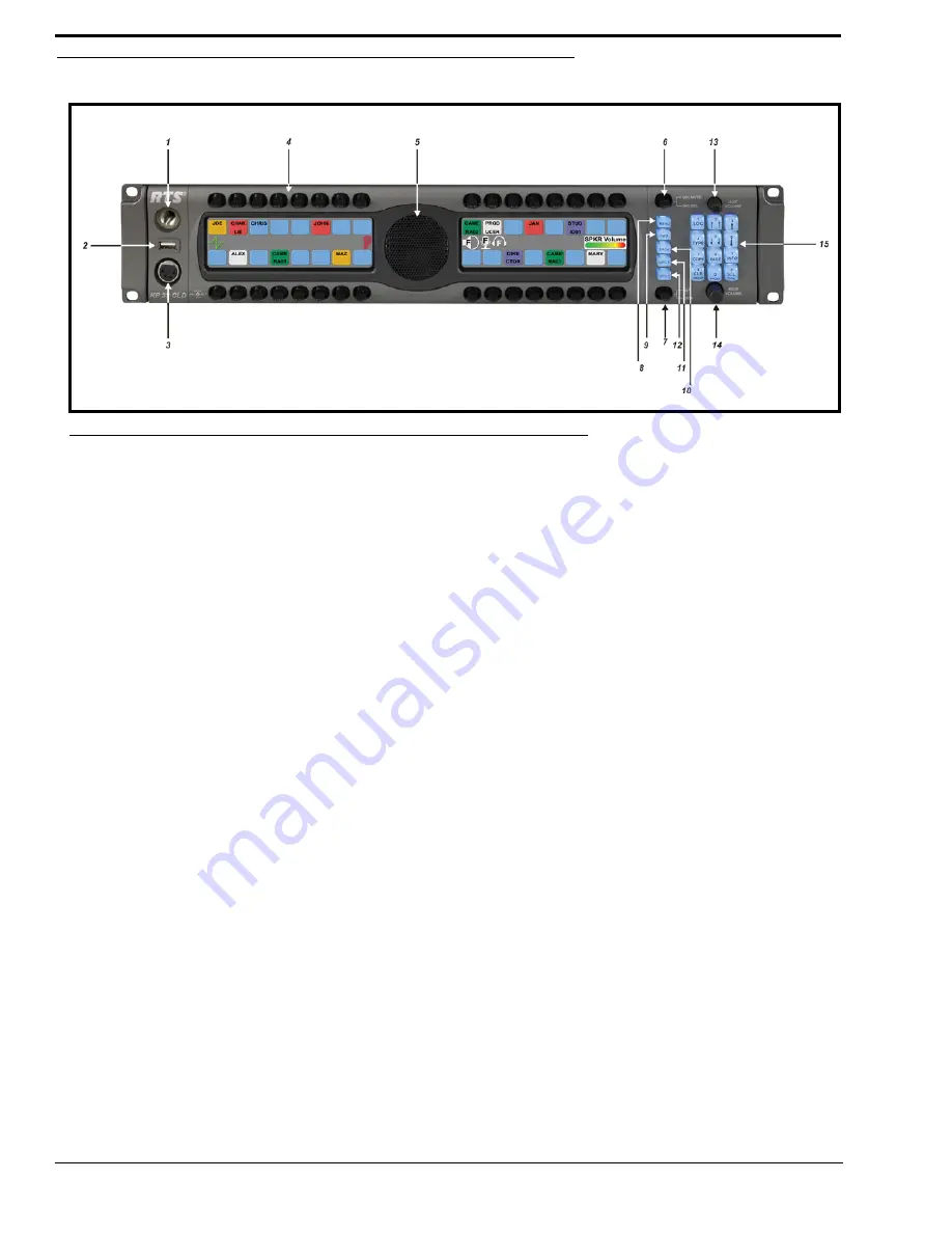
Reference View - KP 32 CLD (90007858000)
Front Panel Descriptions
1.
1 1/4” Stereo Jack - Panel Mic
2.
USB - Data Storage
3.
4- or 5-pin XLR(female) - Headset only connection
6- or 7-pin XLR (female) - Headset and Footswitch connection.
4.
Keypanel Keys - Press down to talk, press up to listen. For more information, see “Basic Intercom Key Operation” on
page 28
5.
Panel Speaker - For more information, see “Mute the Microphone/Speaker” on page 34
6.
Mic Mute / Mic Sel - When the key is pressed up, all active mics are muted. When the key is pressed down the focus
switches between the selected headset or panel mic.
NOTE:
Panel Mic indicates front or rear panel mic. Or, it indicates the front or rear headset speaker. The
configuration of this feature is dependent upon the Audio Out configuration (see “Audio Options Menu,
Speaker” on page 74).
7.
CLR/CWW Key - Clears the panel menu or answers the call waiting window.
8.
Menu button - For detailed explanation, see “KP 32 CLD Menu System” on page 47.
9.
FWD button - Allows you to go forward in the menu structure.
10.
BACK button - Allows you to go backward in the menu structure.
11.
UPG 1 button - The user can assign any function from the menu structure to this key.
12.
UPG 2 button - The user can assign any function from the menu structure to this key.
13.
Aux Volume - The Aux volume adjusts the volume of the Aux 1 through Aux 6 connections, the Matrix connections,
and input channels from the option card (future). The range for this feature is
Mute, -48dB to 10dB
.
14.
Main Volume - The main volume adjusts the volume for the front speaker, rear speaker, front headset and rear
headset.
15.
Keypad - The keypanel keypad is used to navigate through the KP 32 CLD menu structure, configure keypanel
features, as well as utilize the TIF dial-out features.
FIGURE 2.
KP 32 CLD Front Panel
Summary of Contents for CLD Color Keypanel Family DKP 16 CLD
Page 1: ...CLD Color Keypanel Family User Manual 93507858000 Rev B 8 2008 KP 32 CLD DKP 16 CLD EKP 32 CLD...
Page 8: ......
Page 11: ...5 KP 32 CLD Block Diagram FIGURE 1 KP 32 CLD Block Diagram...
Page 26: ...20...
Page 47: ...41 NOTE The KP 32 CLD resets itself once the firmware download is complete...
Page 52: ...46...
Page 55: ...49 FIGURE 23 Main Audio Options Menu...
Page 142: ...136...
Page 143: ...137 CHAPTER 8 Keypanel Menu Quick Reference...
Page 146: ...140 FIGURE 144 Service Menu for the KP 32 CLD with GPI 32 CLD Option card installed...
Page 150: ...144...
Page 154: ...148...
Page 156: ...150...
Page 160: ......


