82
Laser Seam Tracking System for Welding Automation. RF627Weld Series
RF627Weld [Revision 1.1.1] 03.08.2020
5. Start
Riftek Lamia
to perform the calibration:
- Click
SEARCH
to find a scanner.
- Connect to the scanner.
- Go to the
PROTOCOLS
tab and click
LOCK SENSOR
.
- Select
Riftek P2
or
Riftek P3
from a list of protocols.
- Click the
LOAD CALIBRATION OBJECT
button and select the calibration object
file.
- Specify the
Server port
(for
Riftek P2
), or the
Server address
(for
Riftek P3
).
- Enable the
Debug log
option (for
Riftek P2
).
- Enable the
State
option.
- Click the
CALIBRATION
button to open the calibration panel. When the
State
option is enabled, the
Robot data
must show NaN values for each coordinate. If there is
nothing, go back to the
PROTOCOLS
tab, disable the
State
option and enable it again.
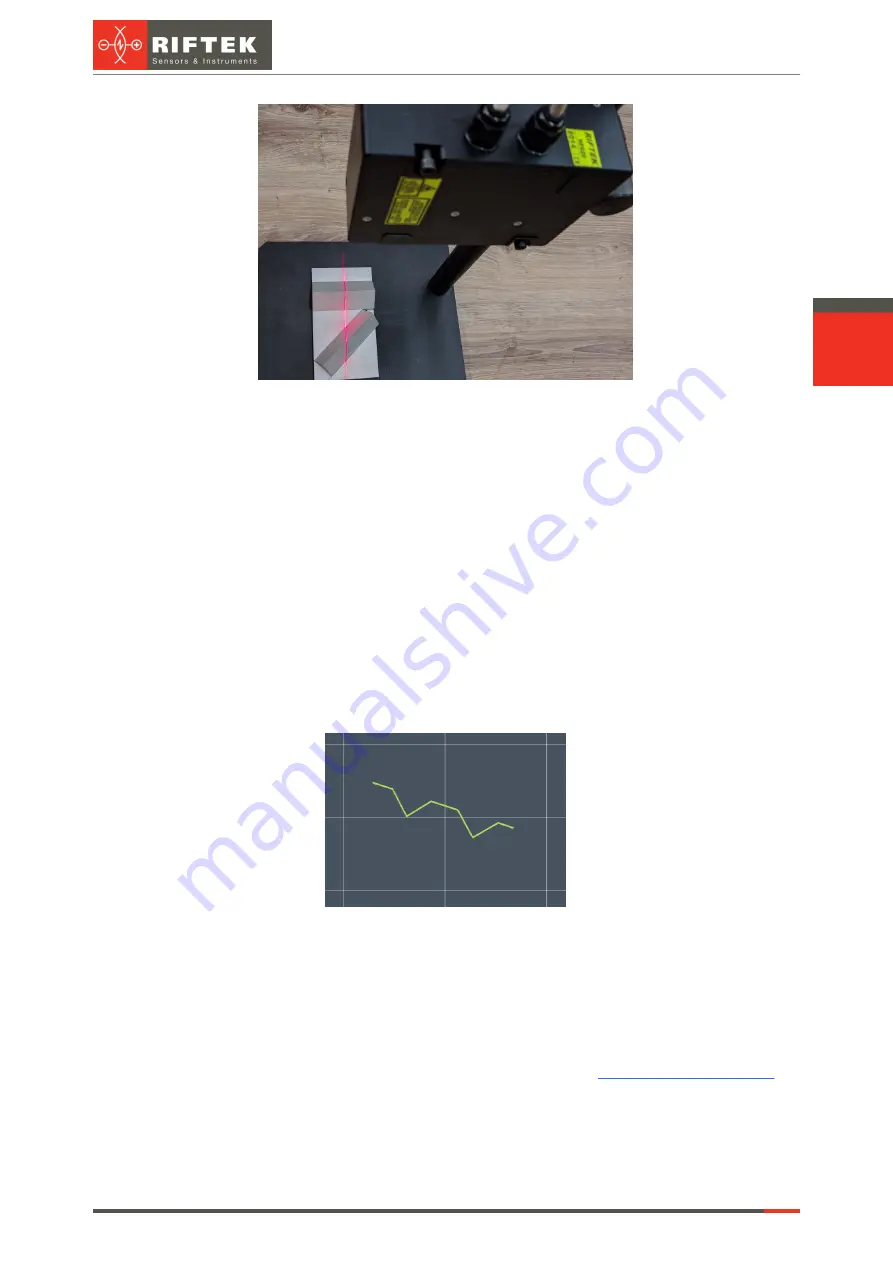
6. Make sure that the current position of the scanner is suitable for calibration (the
program must show "Profile is OK: Yes"). An example of a profile suitable for calibration is
shown in the screenshot below.
7. Click
CAPTURE
. The pair "Robot coord profile" will appear below the
buttons.
8. Change the position of the scanner to the most different from the previous ones
(be sure to use all the angles and coordinates).
9. Repeat steps 6-8 for different positions (from 7 to 10).
10. Click
CALIBRATE
(not available when there are less than 3 pairs "Robot
coord profile"). The calibration process may take a long time.
11. If the result is "Success", make sure that the values of
do
not exceed the maximum valid values. Otherwise, it will be necessary to repeat the
calibration.
12. The calibration is complete.
For every request from a robot, a scanner gives XYZ coordinates of the found point
into the first three registers (in a robot coordinate system), and XZ coordinates of the found


