4.System Maintenance
130
The User manual also recommends site administrators to ask technical support in advance if
the restoration will be necessary.
This procedure overwrites all data, customizations and software updates applied to the E-25C
including any backup images stored locally. Restoring a factory default image will delete all
data.
A customized image can only be restored to the same E-25C unit from which it was created.
1.
Connect the external USB flash drive containing the image to the port on the E-25C.
2.
In WebTools, click Fiery System Restore > Restore.
3.
If you are prompted to login, enter "admin" in the first line, and then the password (Default
password is "Fiery.1".)
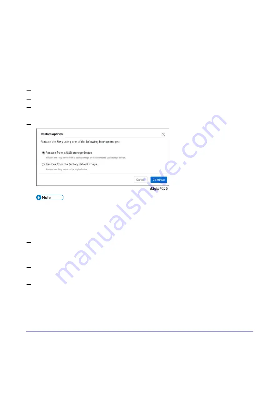
4.
Select the location of the backup file to restore.
If there is no backup created on the internal HDD, Restore from local image will not
appear on the list.
If more than one backup files exists on the USB flash drive, you will be prompted to
choose either file after you click Continue.
5.
Follow the on-screen prompts to complete the restoration.
For restoration using USB 3.0, it will take 10-20 minutes to complete the restoration. When the
restoration is complete, the E-25C will automatically reboot and enter Idle.
6.
Optional: After restoring the E-25C, run System Updates to ensure the latest E-25C software
version is installed.
7.
Optional: If a backup of the configuration settings is available, restore the configuration settings as
described in this document. [Link to
This can be useful if the configuration backup is more current than the system image backup (for
example, when restored to the factory default) or if the configuration backup includes the job log
and VDP/FreeForm Resources.
Restoring the E-25C System Directly with a USB Flash Drive and Service Switch
If a backup was created with Fiery System Restore in the following method, the backup contained in the
USB flash drive can be restored directly with the USB flash drive and the service switch on the E-25C.
This will be useful when having to recover from a system corruption or failure, or if the HDD had been
Summary of Contents for D3GF
Page 2: ......
Page 6: ......
Page 13: ...1 Installation 7 Installation Flow Chart Recommended installation steps are as follows ...
Page 46: ...1 Installation 40 If activation does not require a restart Server Option Client Option ...
Page 71: ...3 Replacement 65 Cover Removal Side Cover for the E 25C 1 Remove the side cover A ...
Page 93: ...4 System Maintenance 87 Command WorkStation For details refer to the Command WorkStation help ...
Page 187: ...7 Specifications 181 H 4 9 x 14 3 x 11 6 Weight 5 5 kg 12 2 lb ...


