


6.9 System checks
GPS Check
GPS selection
You can use an internal (if available) or external GPS receiver.
• Your multifunction display may feature an internal GPS receiver.
• You can also connect an external GPS receiver using SeaTalk
ng
or NMEA 0183.
• Where appropriate use the System Settings menu to enable or
disable the internal GPS receiver.
Enabling or disabling the internal GPS
If your multifunction display features an internal GPS then this can
be enabled and disabled by following the steps below.
With the homescreen displayed:
1. Select
Set-Up
.
2. Select
System Settings
.
3. To enable the internal GPS, select
Internal GPS
so that On is
highlighted.
4. To disable the internal GPS, select
Internal GPS
so that Off
is highlighted.
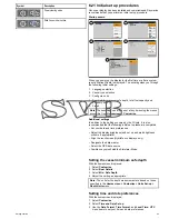
Checking GPS operation
You can check that the GPS is functioning correctly using the chart
application.
1. Select the Chart page.
2. Check the screen.
With the chart displayed, you should see:
Your boat position (indicates a GPS fix)
. Your current position
is represented by a boat symbol or solid circle. Your position is
also displayed in the data bar under VES POS.
A solid circle on the chart indicates that neither heading nor
Course Over Ground (COG) data is available.
Note:
Raymarine recommends that you check the displayed
vessel position in the chart application against your actual
proximity to a known charted object. GPS receivers typically have
an accuracy of between 5 and 15 m.
Note:
A GPS Status screen is available within the Setup menu of
Raymarine multifunction displays. This provides satellite signal
strength and other relevant information.
GPS setup
The GPS setup options enable you to configure a connected GPS
receiver.
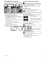
The Global Positioning System (GPS) is used to position your vessel
on the chart. You can set up your GPS receiver and check its status
from the GPS Status option in the
System Settings
menu. For
each tracked satellite, the screen provides the following information:
• Satellite number.
• Signal strength bar.
• Status.
• Azimuth angle.
• Elevation angle.
• A sky-view to show the position of tracked satellites.
D12204-1
6
1
4
2
3
5
Item
Description
1
Sky view
— a visual representation of the position of tracked
satellites.
2
Satellite status
— displays the signal strength and status of
each satellite identified in the sky view diagram on the left of the
screen. The colored bars have the following meanings:
• Grey = searching for satellite.
• Green = satellite in use.
• Orange = tracking satellite.
3
Horizontal Dilution of Position (HDOP)
— a measure of
GPS accuracy, calculated from a number of factors including
satellite geometry, system errors in the data transmission and
system errors in the GPS receiver. A higher figure signifies a
greater positional error. A typical GPS receiver has an accuracy
of between 5 and 15 m. As an example, assuming a GPS
receiver error of 5 m, an HDOP of 2 would represent an error
of approximately 15 m. Please remember that even a very
low HDOP figure is NO guarantee that your GPS receiver is
providing an accurate position. If in doubt, check the displayed
vessel position in the chart application against your actual
proximity to a known charted object.
4
Fix status
— indicates the actual mode the GPS receiver is
reporting (No Fix, Fix, D Fix or SD Fix).
5
Mode
— the mode currently selected by the GPS receiver.
6
Datum
— The GPS receiver's datum setting affects the
accuracy of the vessel position information displayed in the chart
application. In order for your GPS receiver and multifunction
display to correlate accurately with your paper charts, they must
be using the same datum.
The accuracy of the GPS receiver depends on the parameters
detailed above, especially the azimuth and elevation angles which
are used in triangulation to calculate your position.
Radar check
Warning: Radar scanner safety
Before rotating the radar scanner, ensure all personnel
are clear.
Warning: Radar transmission safety
The radar scanner transmits electromagnetic energy.
Ensure all personnel are clear of the scanner when
the radar is transmitting.
Checking the radar
From the Radar application:
1. Select
Menu
.
2. Select
Power
so that On is highlighted.
The Radar scanner will now initialize in standby mode. This
process will take approximately 70 seconds.
Getting started
71
Summary of Contents for A65
Page 2: ......
Page 4: ......
Page 8: ...8 New a Series New c Series New e Series...
Page 12: ...12 New a Series New c Series New e Series...
Page 20: ...20 New a Series New c Series New e Series...
Page 36: ...36 New a Series New c Series New e Series...
Page 64: ...64 New a Series New c Series New e Series...
Page 86: ...86 New a Series New c Series New e Series...
Page 96: ...96 New a Series New c Series New e Series...
Page 106: ...106 New a Series New c Series New e Series...
Page 138: ...138 New a Series New c Series New e Series...
Page 192: ...192 New a Series New c Series New e Series...
Page 202: ...202 New a Series New c Series New e Series...
Page 206: ...206 New a Series New c Series New e Series...
Page 218: ...218 New a Series New c Series New e Series...
Page 228: ...228 New a Series New c Series New e Series...
Page 232: ...232 New a Series New c Series New e Series...
Page 242: ...242 New a Series New c Series New e Series...
Page 248: ...248 New a Series New c Series New e Series...
Page 286: ...286 New a Series New c Series New e Series...
Page 300: ...300 New a Series New c Series New e Series...
Page 307: ......
Page 308: ...www raymarine com...


