PCC-IV Instruction Manual (rev. 0.2)
Page 5-7
Section 5 – Configuring Blockware
Anatomy of a Block
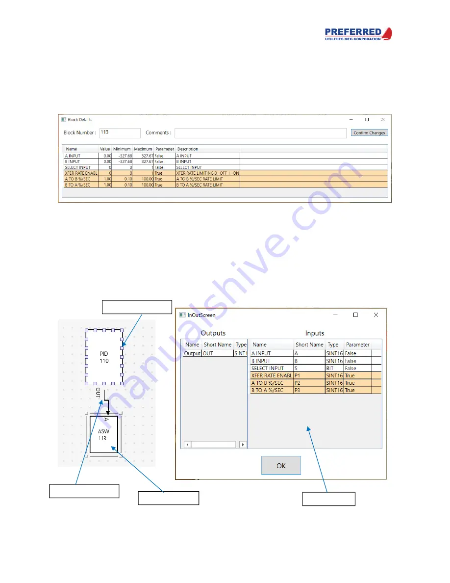
Blocks can be dragged from the right onto the workspace. Double click on the block to open a block details window
which allows you to see its inputs and parameters, set its block number, set parameter values, and see their
minimum and maximum ranges. A comments block is available to leave notes. After making changes, click the
Confirm Changes
button. If nothing is connected to a block’s input or parameter, it will default to 0% for analog
inputs and logic 0 for digital inputs, and Parameters will be what you set them to here (see Connection Points and
Softwiring below). See Section 6 for a full description of each block’s inputs and parameters.
A block can also be resized to make it easier for the programmer to visualize the Blockware or if more connection
points are needed.
Connection Points and Softwiring
To connect one block to another, hover the mouse cursor over the edge of a block and connection points will appear.
Hold the left mouse button and drag the line that appears (softwire) from the source block to the destination block.
An
InOutScreen
pop-up will appear asking you which output and input you are trying to connect. Select the correct
points and click OK.
Connection Points
Softwire Connector
InOutScreen
Function Block


