PCC-IV Instruction Manual (Rev. 0.1)
Page 6-32
Section 6
– Blockware Functions
Technical Reference
Are Bias Resistors Required for Positioner Mode Fault Detection? If 0V and +5V position feedback pot voltages
correspond to a Scaled Position outside the -5% to +105% range, Bias resistors are NOT required. If 0V and +5V
correspond to a Scaled Position inside the -5% to +105% range, Bias resistors ARE required. Preferred Instruments
model DM-1E-P1 actuators (90 deg stroke) do NOT require Bias resistors, Preferred model R-AL actuators DO
require 75-ohm Bias resistors.
The best way to determine if Bias resistors are required with other actuators is to install the actuator, stroke it,
Calibrate the Scaled Position (see above), and then test the actuator for proper Fault Detection (see below for
procedure). When in doubt, install Bias Resistors (if Fault Detection is required).
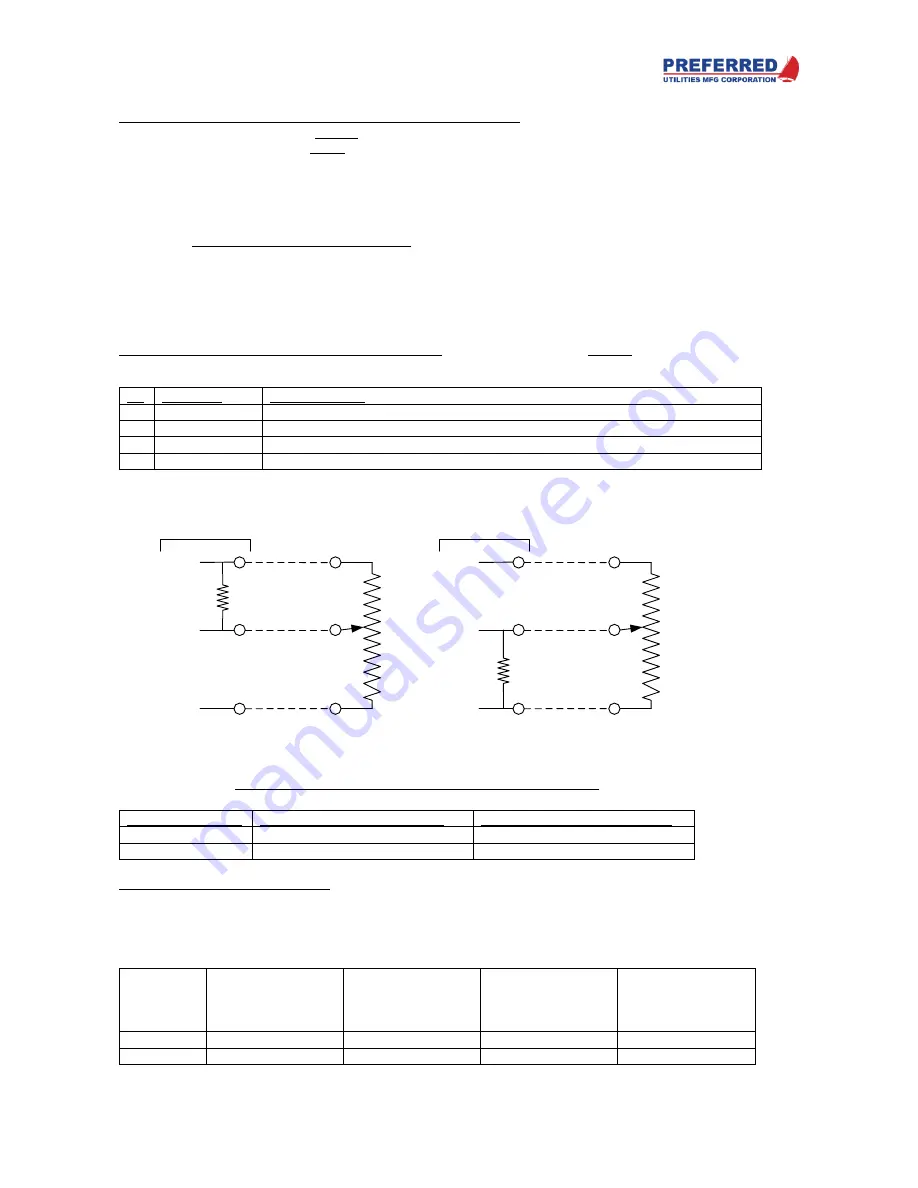
See the schematic above for Bias resistor wiring. Use metal film or wire wound Bias Resistors (for low temperature
drift), carbon composition or carbon film resistors should not be used if the ambient temperature changes
substantially. The Bias resistance should be approximately 7% (or more) of the feedback pot element's actual
resistance (some pots have a +/- 20% tolerance).
Fail Mode: STOP, INC, DEC, DISABLE (Parameter 8): If the Scaled Position is outside the -5% to +105% range for
more than P9 seconds, TOUT activates the triacs per the mode selected by P8:
P8
Fail Mode
Triac Response
0
STOP
Both triacs are turned OFF.
1
INC
INCREASE triac is turned ON, DECREASE triac is turned OFF
2
DEC
DECREASE triac is turned ON, INCREASE triac is turned OFF
3
DISABLE
The Fault is ignored. The triacs respond to the normal
TOUT
PV and SP logic
During the P9 time delay, the triacs respond to the normal
TOUT
PV and SP logic. Wire the Feedback Pot
as indicated below to achieve the desired response during the P9 time delay:
Desired Response:
Connect Pot "Increase" end to:
Connect Pot "Decrease" end to:
Fail Close
+5 V
"-" (Signal Common)
Fail Open
"-" (Signal Common)
+5 V
Test Feedback Pot Fault Detection: Install the actuator, stroke it, Calibrate the Scaled Position (see above), and
then test the Feedback Pot Fault Detection. The block outputs of TOUT, TTRIP, and TCODE must be monitored
during the test. Frequently these are Front Panel Display channels; if not, consult the Blockware drawing to find the
block numbers and use the Utilities / Examine menu (see Section 4) to display the values.
Disconnect one feedback pot wire at a time, leaving the other two wires connected. Verify the following:
Open
Pot Wire
TOUT
for
"Fail Closed Wiring"
(+5 V = Increase)
TCODE
for
"Fail Closed Wiring"
(+5 V = Increase)
TOUT
for
"Fail Open Wiring"
(+5 V = Decrease)
TCODE
for
"Fail Open Wiring"
(+5 V = Decrease)
Increase
less than -5%
2.00 %
less than -5%
2.00 %
Wiper
greater than +105%
1.00 %
less than -5%
2.00 %
"PULL-UP" WIRING FOR "FAIL-CLOSED" AND "FAIL-OPEN" SYSTEMS
FEEDBACK
POT
+ 5 V
AIN
SIGNAL
"-"
PULL-UP
RESISTOR
PCC-III-Gxx0
'
Fail Closed
' Pull-up Wiring.
If Wiper Opens:
AIN = +5V (> 100%), Decrease Triac turns ON
INCREASE
DECREASE
A
B
C
WIPER
FEEDBACK
POT
+ 5 V
AIN
SIGNAL
"-"
PULL-UP
RESISTOR
PCC-III-Gxx0
'
Fail Open
' Pull-up Wiring.
If Wiper Opens:
AIN = +5V (< 0%), Increase Triac turns ON
INCREASE
DECREASE
A
B
C
WIPER


