


76
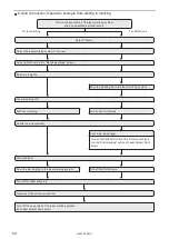
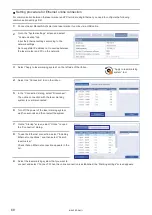
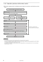
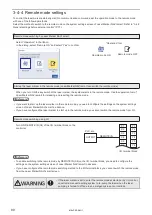
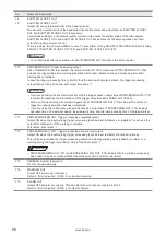
3-4-2 Operation procedure with external control
⿎
Operation example when controlling the laser marker from external control devices such as
PLC
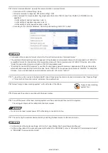
Refer to “3-4-4 Remote mode settings” (P.80).
The device is ready for receiving the marking starting signal (trigger).
Turn ON key switch of laser marker controller
Marking
Control by communication
commands
I/O control
OPEN shutter
Remote mode ON
Select file
Confirm READY OUT is ON.
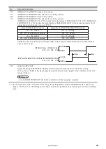
Trigger Input ON
Laser pumping ON
Control by using I/O or
communication commands
ンㄆㄇㄆㄓㄆㄏㄆ
• It is available to the external control combining I/O, and communication commands.
• You need to configure the system settings on the I/O communication in advance before using external control. Refer to
“3-4-3 General settings before external control” (P.77).
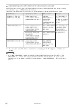
• For details on the operation procedure when you link an image checker or a code reader, refer to “6 Link Control with
ME-LPRF-SM-11
Summary of Contents for LP-RF Series
Page 17: ...1 Product Overview ME LPRF SM 11...
Page 34: ...2 Laser Marker Installation ME LPRF SM 11...
Page 57: ...3 Operation Method ME LPRF SM 11...
Page 81: ...4 External Control Using I O ME LPRF SM 11...
Page 126: ...5 External Control by Communication Commands ME LPRF SM 11...
Page 135: ...6 Link Control with External Devices ME LPRF SM 11...
Page 160: ...7 Maintenance ME LPRF SM 11...
Page 186: ...Troubleshooting ME LPRF SM 11...
Page 214: ...Index ME LPRF SM 11...
Page 216: ...216 USB 32 55 W Warning 205 ME LPRF SM 11...
Page 217: ......


