


116
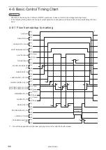
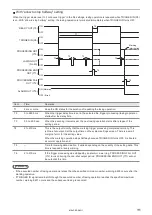
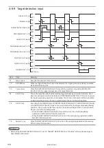
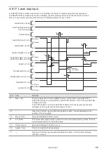
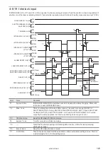
4-6-9 Target detection input
TRIGGER IN (X5)
PROCESSING OUT (Y10)
TARGET DETECTION IN (X7)
PROCESSING END OUT (Y11)
PROCESSING FAIL OUT (Y12)
CHECK OK OUT (No.34)
CHECK NG OUT (No.35)
WARNING OUT (Y14)
LASING OUT (No.40)
READY OUT (Y5)
ON
OFF
ON
OFF
ON
OFF
ON
OFF
ON
OFF
ON
OFF
ON
OFF
ON
OFF
ON
OFF
ON (Normal)
OFF (Error)
T2
T1
T2
T3
T2
T4
T4
T4
T5
T5
T5
T1
T6
T3
Item
Time
Remarks
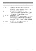
T1
2ms or more
Keep the ON status for 2ms or more.
T2
0 to 9999 ms
When the trigger delay time is set in the selected file, trigger processing (lasing) operation
starts after the delay time.
T3
1 ms or more
When TARGET DETECTION IN (X7) turns ON for more than 1ms while LASING OUT
(No.40) is ON, it is judged as success of the target detection.
T4
2 to 510 ms
This is the output to notify that the marking trigger processing completed normally. Even
when the workpiece could not be detected, PROCESSING END OUT (Y11) turns on unless
the trigger processing operation is interrupted. This is One-shot output. Set the output time
on System settings screen. There is a small margin of error for the setting value.
T5
2 to 510 ms
According to the ON/OFF state of TARGET DETECTION IN (X7), CHECK OK OUT (No.34)
or CHECK NG OUT (No.35) turns on for one-shot time after the trigger processing (lasing)
operation. The one-shot output time is set on the system settings screen. There is a small
margin of error for the setting value.
• When TARGET DETECTION IN (X7) turns ON for more than 1ms during lasing
operation: CHECK OK OUT (No.34) turns ON.
• When TARGET DETECTION IN (X7) did not turn ON during lasing operation: CHECK
NG OUT (No.35) turns ON.
T6
Approx. 3 sec.
When TARGET DETECTION IN (X7) did not turn ON during lasing operation, the warning
E752 is output for 3 seconds.
ンㄆㄇㄆㄓㄆㄏㄆ
• Before using TARGET DETECTION IN (X7), set X7: TARGET DETECTION IN to “Enabled” at the system settings of
Laser Marker NAVI smart.
ME-LPRF-SM-11
Summary of Contents for LP-RF Series
Page 17: ...1 Product Overview ME LPRF SM 11...
Page 34: ...2 Laser Marker Installation ME LPRF SM 11...
Page 57: ...3 Operation Method ME LPRF SM 11...
Page 81: ...4 External Control Using I O ME LPRF SM 11...
Page 126: ...5 External Control by Communication Commands ME LPRF SM 11...
Page 135: ...6 Link Control with External Devices ME LPRF SM 11...
Page 160: ...7 Maintenance ME LPRF SM 11...
Page 186: ...Troubleshooting ME LPRF SM 11...
Page 214: ...Index ME LPRF SM 11...
Page 216: ...216 USB 32 55 W Warning 205 ME LPRF SM 11...
Page 217: ......


