


37
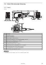
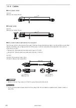
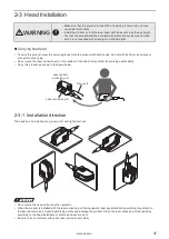
2-3 Head Installation
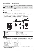
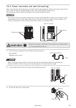
WARNING
• Make sure that the power is turned OFF at installing. Failure to do so may
cause electrical shock.
• Install the product so that the laser beam path does not cross the eye height.
• The laser beam path shall be enclosed with protective enclosure and make
sure it is not exposed with direct light or reflected light.
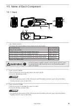
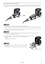
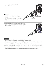
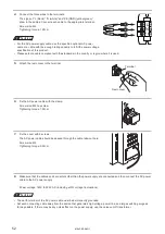
Carrying head part
• To carry this product, wear the non-slip gloves. Hold the product with both hands. Do not hold the fiber unit, cables or
connectors at carrying.
• Do not touch the laser emission port on the bottom of the head. It may affect the marking quality badly.
• Carry this product as shown in the figure below.
Laser emission port
Laser pointer
emission port
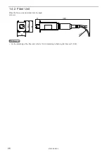
Fiber unit
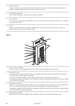
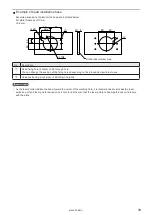
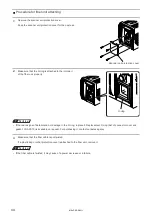
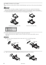
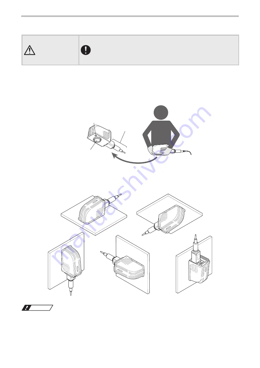
2-3-1 Installation direction
The head can be installed to up, down, left, and right directions.
ワㄐㄕㄊㄆ
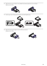
• Do not move the head unit during the operation.
• When the product is installed with the laser emission port facing upward, dust generated during marking may attach to
the laser emission port, impairing marking quality and damage the product. Clean the laser emission port periodically
according to the head installation conditions and environment.
• Be sure to fix the bottom surface (the laser emission port side).
ME-LPRF-SM-11
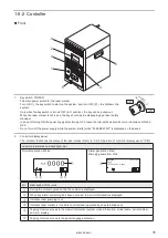
Summary of Contents for LP-RF Series
Page 17: ...1 Product Overview ME LPRF SM 11...
Page 34: ...2 Laser Marker Installation ME LPRF SM 11...
Page 57: ...3 Operation Method ME LPRF SM 11...
Page 81: ...4 External Control Using I O ME LPRF SM 11...
Page 126: ...5 External Control by Communication Commands ME LPRF SM 11...
Page 135: ...6 Link Control with External Devices ME LPRF SM 11...
Page 160: ...7 Maintenance ME LPRF SM 11...
Page 186: ...Troubleshooting ME LPRF SM 11...
Page 214: ...Index ME LPRF SM 11...
Page 216: ...216 USB 32 55 W Warning 205 ME LPRF SM 11...
Page 217: ......


