


194
Troubles
Causes
Measures
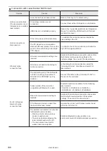
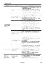
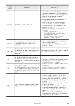
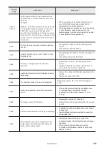
Characters are distorted.
Character pitch is
unstable.
When Line speed control is set
to Encoder input:
The line speed could not be
measured correctly by the
encoder.
• Make sure that the encoder operates properly.
• Make sure that the setting value of Encoder resolution
is correct.
• When using A phase only:
Encoder resolution = Number of pulses/mm x 2
• When using A and B phases:
Encoder resolution = Number of pulses/mm x 4
• When only one phase of the encoder is used, connect
the encoder signal to ENCODER A IN (X13) and
connect ENCODER B IN (X14) to IN COM. 1 (X2).
When Line speed control is set
to Encoder input:
The input speed of the encoder
is not consistent with the actual
line speed at marking.
• Place the encoder closer to the trigger sensor.
• Adjust the setting value of Encoder resolution by
checking the marking quality.
• When the character spacing is too wide:
Increase the setting.
• When the character spacing is too narrow:
Decrease the setting.
• In some cases, it may reduce the influence of the ups
and downs of the line speed to decrease the encoder
resolution. However, it is recommended to set more
than 25pulses/mm to Encoder resolution.
When Line speed control is set
to 2 sensors input:
The line speed could not be
measured correctly by the two
sensors.
• Check the setting value of Distance line speed
sensors.
• Confirm the sensors for line speed detection operate
properly.
When Line speed control is set
to 2 sensors input:
The input speed of the 2
sensors is not consistent with
the actual line speed at marking.
• Place the trigger sensor closer to the line speed
detection sensors so that the difference of the speed
at detection and at marking may reduce.
• Adjust the setting value of Distance line speed
sensors by checking the marking quality.
• When the character spacing is too wide:
Increase the setting.
• When the character spacing is too narrow:
Decrease the setting.
ME-LPRF-SM-11
Summary of Contents for LP-RF Series
Page 17: ...1 Product Overview ME LPRF SM 11...
Page 34: ...2 Laser Marker Installation ME LPRF SM 11...
Page 57: ...3 Operation Method ME LPRF SM 11...
Page 81: ...4 External Control Using I O ME LPRF SM 11...
Page 126: ...5 External Control by Communication Commands ME LPRF SM 11...
Page 135: ...6 Link Control with External Devices ME LPRF SM 11...
Page 160: ...7 Maintenance ME LPRF SM 11...
Page 186: ...Troubleshooting ME LPRF SM 11...
Page 214: ...Index ME LPRF SM 11...
Page 216: ...216 USB 32 55 W Warning 205 ME LPRF SM 11...
Page 217: ......


