


212
ERROR
CODE
Description
Measures *1
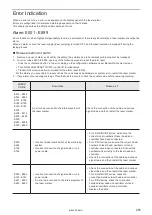
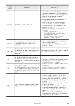
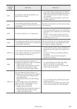
E686
Any of the following functions that are not
available with the seamless loop setting are
configured.
• Multiple objects
• Object consisting of unclosed line(s)
• Point radiation object
• Step & repeat function
• Deactivate the seamless loop in the laser settings.
• If you want to radiate laser continuously without
any break, set the closed line by setting the start
and end points in the same position.
E687
Graphic object contains an invalid setting.
• Reduce the graphic size. The graphic width or
height should be less than 999.999 mm.
• If the “Graphic presets” is off, set on for “Adjustment
of size and filling” in the graphic object settings and
specify the graphic parameters in the “Marking
settings” screen.
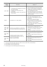
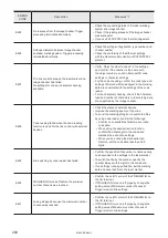
E699
Some setting fields contain an improper value.
• Overwrite the data again to the selected file
number.
• If the problem persists, save the backup file and
contact our sales office or representatives.
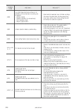
E710 - E711
The head air-cooling fan has stopped.
• Refer to “Setup/Maintenance Guide” and clean the
fan.
• Check the connection status of the fan connector.
• Replace the fan.
• For LP-RC series, confirm the side covers of the
head are installed properly.
E715 *3
The temperature of the laser oscillator is high.
• Check if the ambient temperature of the
laser marker is not exceeding the range of its
specification.
• Make sure air-cooling fan operates.
• Remove the dust and contamination in the air
intake and exhaust port, and clean the air-cooling
part such as fan and filter.
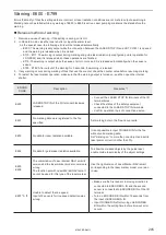
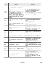
E750
Invalid trigger signal.
TRIGGER IN was input during trigger
processing.
• Turn ON TRIGGER IN after confirming READY
OUT is ON.
• Do not input the marking trigger while
PROCESSING OUT is ON.
• Check the switch or the sensor connected to
TRIGGER IN of I/O terminal operates properly
without chattering.
• Check wiring of I/O or communication port to the
external control devices.
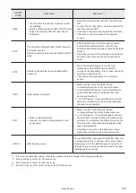
E751
Invalid trigger signal.
TRIGGER IN was input while READY OUT is
OFF.
E752 *3, *4
TARGET DETECTION IN did not turn ON during
the lasing process.
• Check the marking results before and after the
error.
• Check the connection and control method of the
work detection sensor.
• Set the work detection sensor position so that the
sensor turns ON more than 1ms during marking.
• When you do not use this function, set “Disable” at
X7: TARGET DETECTION IN with Laser Marker
NAVI smart system settings.
ME-LPRF-SM-11
Summary of Contents for LP-RF Series
Page 17: ...1 Product Overview ME LPRF SM 11...
Page 34: ...2 Laser Marker Installation ME LPRF SM 11...
Page 57: ...3 Operation Method ME LPRF SM 11...
Page 81: ...4 External Control Using I O ME LPRF SM 11...
Page 126: ...5 External Control by Communication Commands ME LPRF SM 11...
Page 135: ...6 Link Control with External Devices ME LPRF SM 11...
Page 160: ...7 Maintenance ME LPRF SM 11...
Page 186: ...Troubleshooting ME LPRF SM 11...
Page 214: ...Index ME LPRF SM 11...
Page 216: ...216 USB 32 55 W Warning 205 ME LPRF SM 11...
Page 217: ......


