


92
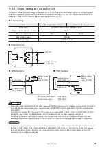
Input signal operation on the I/O connector
ンㄆㄇㄆㄓㄆㄏㄆ
• The ON/OFF listed in this section refers to the ON/OFF operations. It does not refer to the voltage level (High/Low).
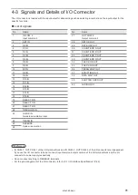
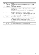
No.
Name and description
1
IN COM. 2: Input common 2
The common terminal for each input of the I/O connector.
For NPN connection, this terminal is connected to the “+ (plus)” side of power which is used for control. For
PNP connection, this terminal is connected to the “- (minus)” side of power which is used for control.
ンㄆㄇㄆㄓㄆㄏㄆ
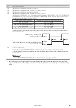
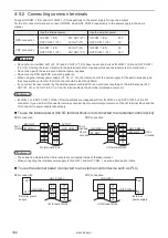
• IN COM. 1, OUT COM. 1 of the I/O terminal block and IN COM. 2, OUT COM. 2 of the I/O connector are
independent.
If you use the I/O connector terminal, connect input common/output common of the I/O terminal block and
the I/O connector to power supply respectively.
• For details on the connection, refer to “4-5-2 Connecting common terminals” (P.102).
2
SET IN
Turn ON this signal when executing the input of D0 IN to D15 IN (No.3 to 18) and SELECT 0 IN to SELECT 2
IN (No.19 to 21).
Turn ON SET IN with maintaining the input status of D0 IN to D15 IN and SELECT 0 IN to SELECT 2 IN. The
input operation is executed at the timing of the edge of turning ON.
SET IN is required to control the following operations by I/O.
• Select file number
• Correct the count-up/count-down value of the counter function
• Reset the count value of the counter function
• Switch marking characters of the registered characters via I/O
• Switch marking position of the external offset function
3 to 18
D0 IN to D15 IN : Number input
Set the number for one of the following targets selected at SELECT 0 IN to SELECT 2 IN (No.19 to 21).
q
File No.
w
Count-up value correction
e
Count-down value correction
r
Counter number to reset
t
Data number for the registered characters/external offset function
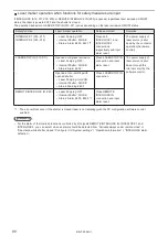
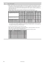
q
File No. (SELECT 0 IN to SELECT 2 IN: All OFF)
Input when changing the file number of 0 to 9999.
Specify the file number in the binary system as D0 to D15 and turn ON SET IN (No.2).
Indicate values in the binary system as ON/OFF of D0 to D15 with D0 being the lowest digit value.
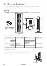
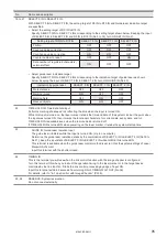
Example: When selecting the file No. 618
Select “0000 0010 0110 1010”, which represents 618 in a 16-bit binary system, by specifying ON/OFF of
D0 to D15 as shown in the below table.
Terminal
File No. (binary)
Input
D0
0
OFF
D1
1
ON
D2
0
OFF
D3
1
ON
D4
0
OFF
D5
1
ON
D6
1
ON
D7
0
OFF
Terminal
File No. (binary)
Input
D8
0
OFF
D9
1
ON
D10
0
OFF
D11
0
OFF
D12
0
OFF
D13
0
OFF
D14
0
OFF
D15
0
OFF
ME-LPRF-SM-11
Summary of Contents for LP-RF Series
Page 17: ...1 Product Overview ME LPRF SM 11...
Page 34: ...2 Laser Marker Installation ME LPRF SM 11...
Page 57: ...3 Operation Method ME LPRF SM 11...
Page 81: ...4 External Control Using I O ME LPRF SM 11...
Page 126: ...5 External Control by Communication Commands ME LPRF SM 11...
Page 135: ...6 Link Control with External Devices ME LPRF SM 11...
Page 160: ...7 Maintenance ME LPRF SM 11...
Page 186: ...Troubleshooting ME LPRF SM 11...
Page 214: ...Index ME LPRF SM 11...
Page 216: ...216 USB 32 55 W Warning 205 ME LPRF SM 11...
Page 217: ......


