


129
⿎
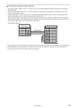
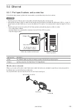
Connecting to external control devices
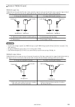
• To connect the laser marker to the PC for control, use a commercially available RS-232C straight cable (laser marker
side: 9pin male).
• In case of connecting to PLC, a type of the cable (straight or cross) differs depending on a manufacturer or a model.
Please follow the PLC manual.
• To connect RS-232C terminal without using a commercially available RS-232C cable, connect only 3 signals of RxD,
TxD and GND and do not use other signals on the laser marker side.
• You may need a signal line connection (loop back line) other than RxD (RD), TxD (SD) or GND on the external control
device side depending on the specifications of the external control device. Read the instruction manual of the external
control device and connect it to the laser marker appropriately.
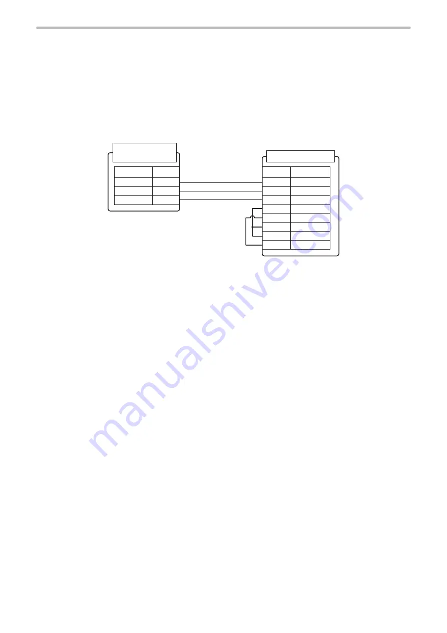
Connection example
RxD
TxD
GND
DCD
DTR
DSR
RTS
CTS
2
3
5
1
4
6
7
8
TxD
RxD
GND
2
3
5
RS-232C port
(Laser marker)
External control devise
Straight cable
Signal
Signal
*
Terminal No.
Terminal No.
* The loop back wiring on the external control device side shown in the above figure is just an example. The wiring method
varies depending on the specifications of each external control device. Read the instruction manual of the external
control device and connect it to the laser marker appropriately.
ME-LPRF-SM-11
Summary of Contents for LP-RF Series
Page 17: ...1 Product Overview ME LPRF SM 11...
Page 34: ...2 Laser Marker Installation ME LPRF SM 11...
Page 57: ...3 Operation Method ME LPRF SM 11...
Page 81: ...4 External Control Using I O ME LPRF SM 11...
Page 126: ...5 External Control by Communication Commands ME LPRF SM 11...
Page 135: ...6 Link Control with External Devices ME LPRF SM 11...
Page 160: ...7 Maintenance ME LPRF SM 11...
Page 186: ...Troubleshooting ME LPRF SM 11...
Page 214: ...Index ME LPRF SM 11...
Page 216: ...216 USB 32 55 W Warning 205 ME LPRF SM 11...
Page 217: ......


