


128
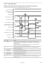
5-2 RS-232C
To control the laser marker by communication commands, use RS-232C or Ethernet connection.
For the control by communication commands, configure the communication settings in advance at the system settings of
Laser Marker NAVI smart. Refer to “3-4-3 General settings before external control” (P.77).
ンㄆㄇㄆㄓㄆㄏㄆ
• The laser marker can be controlled by I/O and communication commands combined.
• For communication commands, refer to “Serial Communication Command Guide”.
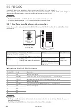
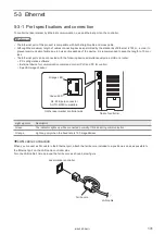
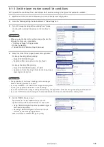
5-2-1 Interface specifications and connection
To execute command communication control with RS-232C, connect the RS-232C port on the controller to the external
control device.
5
9
1
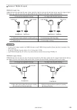
6
RS-232C port
(female)
On the laser marker
controller side
Rear of controller
Connector position
Connector specifications
Model
Manufacturer name
On the laser marker
side
D-sub 9-pin, female
Screw type: No.4-40UNC inch screw, female
-
-
User side
D-sub 9-pin, male
Screw type: No.4-40UNC inch screw, male
Recommended connector
XM3A-0921
OMRON
Corporation
Recommended connector cover
XM2S-0913
⿎
Signals and Details of RS-232C connector
Terminal No.
Signal
Description
1
N.C.
Do not use this signal.
2
TxD (SD)
Transmission data: Connect RxD (RD) of the external control device
3
RxD (RD)
Receiving data: Connect TxD (SD) of the external control device
4
N.C.
Do not use this signal.
5
GND (SG)
Signal ground: Connect GND (SG) of the external control device
6
N.C.
Do not use this signal.
7
N.C.
8
N.C.
9
N.C.
ンㄆㄇㄆㄓㄆㄏㄆ
• On the system settings screen, select communication command control or code reader linkage function that you use
with the RS-232C port.
• The GND pin of the RS-232C connector is common to the body of the laser marker.
ME-LPRF-SM-11
Summary of Contents for LP-RF Series
Page 17: ...1 Product Overview ME LPRF SM 11...
Page 34: ...2 Laser Marker Installation ME LPRF SM 11...
Page 57: ...3 Operation Method ME LPRF SM 11...
Page 81: ...4 External Control Using I O ME LPRF SM 11...
Page 126: ...5 External Control by Communication Commands ME LPRF SM 11...
Page 135: ...6 Link Control with External Devices ME LPRF SM 11...
Page 160: ...7 Maintenance ME LPRF SM 11...
Page 186: ...Troubleshooting ME LPRF SM 11...
Page 214: ...Index ME LPRF SM 11...
Page 216: ...216 USB 32 55 W Warning 205 ME LPRF SM 11...
Page 217: ......


