


179
10.
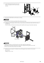
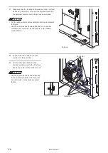
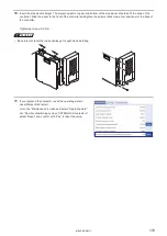
Insert the side panel straight. The projecting part of upper and bottom of the side panel should be fit the drain of the
controller. Slide the panel to the front of the controller and tighten the screws (M3 screws, four positions) of the back of
the controller.
Tightening torque: 0.5 N·m
ワㄐㄕㄊㄆ
• Be careful not to let the inside cables get caught while installing.
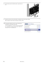
11.
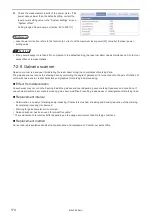
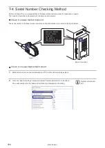
If you replaced the contactor, reset the operating data in
Laser Marker NAVI smart.
Go to the “Maintenance” screen and select “Operating data”.
For “Number of switching cycles of INTERLOCK contactors”,
select “Reset” and confirm with “Yes” to reset the value.
ME-LPRF-SM-11
Summary of Contents for LP-RF Series
Page 17: ...1 Product Overview ME LPRF SM 11...
Page 34: ...2 Laser Marker Installation ME LPRF SM 11...
Page 57: ...3 Operation Method ME LPRF SM 11...
Page 81: ...4 External Control Using I O ME LPRF SM 11...
Page 126: ...5 External Control by Communication Commands ME LPRF SM 11...
Page 135: ...6 Link Control with External Devices ME LPRF SM 11...
Page 160: ...7 Maintenance ME LPRF SM 11...
Page 186: ...Troubleshooting ME LPRF SM 11...
Page 214: ...Index ME LPRF SM 11...
Page 216: ...216 USB 32 55 W Warning 205 ME LPRF SM 11...
Page 217: ......


